Download
1 / 46
460 likes | 470 Views
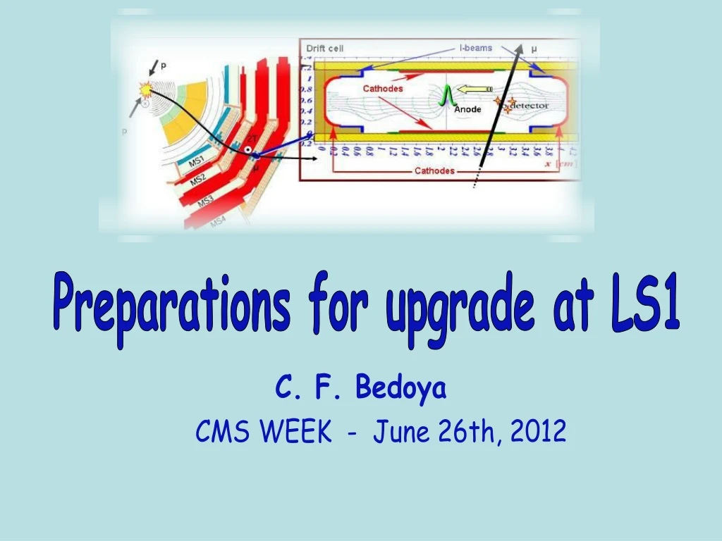
Preparations for upgrade at LS1. C. F. Bedoya. CMS WEEK - June 26th, 2012. C. F. Bedoya June 26th, 2012. 2. Drift Tubes Upgrade Plan. * Theta Trigger Board (TRB) * Sector Collector relocation. LS1. Phase 2. New DTTF?.

E N D
Preparations for upgrade at LS1 C. F. Bedoya CMS WEEK - June 26th, 2012
C. F. Bedoya June 26th, 2012 2 Drift Tubes Upgrade Plan * Theta Trigger Board (TRB) * Sector Collector relocation LS1 Phase 2 New DTTF? Improve maintainability and performance New TSC design + gradual installation Improves maintainability and performance… Future connection to Tracker? Tracker connection New ROS design + gradual installation Bottleneck at increased luminosities
C. F. Bedoya June 26th, 2012 3 CMS Upgrade Organization ~Phase 2 Previous: Track Trigger Task Force M. Mannelli W. Smith O. Buchmüller ~Phase 1 Various forums, scopes are interrelated Muon Long Term strategy working group
C. F. Bedoya June 26th, 2012 4 https://indico.cern.ch/conferenceDisplay.py?confId=191271 Important step in the project • Electronics Change Review (ECR) outcome: • The plan for installation of new infrastructure, appears sound and the project should proceed. • The plan for manufacturing of electronics modules was endorsed subject to actual availability of the optical components. Installation Readiness Review (IRR) in October
C. F. Bedoya June 26th, 2012 5 DT LS 1: SC relocation Goal: Replace SC crate with simple CuOF electronics and place TSC (Trigger Sector Collector) and ROS (Read Out Server) in USC during LS1 -ROS -TSC
CuOF Mezzanine • PROTOTYPE PRODUCED • BEING TESTED AT TORINO, MADRID, BOLOGNA Each CuOF mezzanine contains 8 copper to optical links. electrical input Optical output • Equalizer restores the data quality and the DC balance (LMH0024) • Laser driver (ONET1191) sets the modulation signal for the VCSEL (OPTOWELL TP85-LCP1F). In the same package, a photodiode measures the light for implementing a feedback loop to compensate the laser ageing (operation in closed loop). • The VCSEL diodes connect to fibers through custom LC adapters S. Maselli 6/6/12 DT Sector Collector Re-location ECR 6
CUOF Irradiation at H4IRRAD May-June 2012 The 0th version of mother board • Irradiation conditions expected: • 1012 particles/cm-2 Si 1MeV equivalent neutrons • 7.5 1010 particles/cm2 High Energy Hadrons • 42 Gy Dose • which is approximately more than 30 years HL-LHC • (including uncertainty factor 3.15) First results positive, further report soon The Slow Control with Spartan Xilinx 50 meters Copper cable into target area 50 meters Optical fibers output target area S. Maselli 6/6/12 DT Sector Collector Re-location ECR 7
CuOF Mother Board mechanics Electrical signal (LVDS) enter from the front of the crate through the (up to 40 m) cables that come from the Minicrates. Optical signals through MTP connectors will be extracted from the back of the crate (up to 60 m fibers). The mother board includes 3 fiber patch cords that will connect the mezzanines to an MTP (12 channels) adapters on the back of the board. • Next actions: • Produce a Motherboard prototype • Find adequate fanout S. Maselli 6/6/12 DT Sector Collector Re-location ECR 8
C. F. Bedoya June 26th, 2012 9 DT LS 1: SC relocation Goal: Replace SC crate with simple CuOF electronics and place TSC (Trigger Sector Collector) and ROS (Read Out Server) in USC during LS1 -ROS -TSC
OFCU-TSC produced • Test set-up built • First tests on going R. Travaglini et al 10
R. Travaglini et al -Eye opening quite small, risk of having signal integrity problems -In addition we see some unlock problems with the optical chain -> We need to work on insuring link reliability 11
Tolerable skews – current system June 26th, 2012 12 Trigger links: Skews and fibers lengths All muon barrel sectors Test a@P5 : the TSC mezzanines can reabsorb skews up to ±6.25 ns All 96 fibers inside each Trunk cable < 1.2 ns We should have no problem (we don´t need all 96 fibers within ±6.25 ns either) 12
C. F. Bedoya June 26th, 2012 13 DT LS 1: SC relocation Goal: Replace SC crate with simple CuOF electronics and place TSC (Trigger Sector Collector) and ROS (Read Out Server) in USC during LS1 -ROS -TSC
C. F. Bedoya June 26th, 2012 14 OFCU-RO • First OFCU-RO prototype designed, fabricated and mounted • Problem with the 25th channel Dual receiver: • Communication with distributor and manufacturer didn’t clarify the problem • Falling back to a different solution • Custom backplanes produced and mounted • Mechanical tolerances validated • Further tests waiting for other electronic boards to be ready (VME_patch and TSC_rear) • TSC_rear being mounted • Work at present being done on TSC to ROS link firmware implementation A. Navarro, C. F. Bedoya
C. F. Bedoya June 26th, 2012 15 OFCU-RO: Tests at Lab Minicrate + 40 m LVDS cable (final) + CuOF mezz from Torino + 62 m Fiber from CERN + OFCU-RO + ROS • Detects: unlocks, parity errors, misalignments, etc. (similar to final system) • No real BER test can be performed with this system, but real TDC data is checked at 100 kHz L1A rate (chamber hits can be simulated) • A two-day run test has been done, no errors found but further checks need to be performed Good Images showing the 25th channel problem BAD A. Navarro, C. F. Bedoya
C. F. Bedoya June 26th, 2012 16 DT LS 1: SC relocation Goal: Replace SC crate with simple CuOF electronics and place TSC (Trigger Sector Collector) and ROS (Read Out Server) in USC during LS1 -ROS -TSC
June 26th, 2012 17 DT SC relocation: FIBERS • Purchase CERN Draka 96 cables/fiber in June (THAT IS NOW!!!) • * Purchase in batches: • - Readout fibers • - Trigger fibers (maybe 2 batches) • * Test them (continuity and length) at CERN-TS-EL-OF lab • * Store them in false ceiling of 904 Need to take a decision on fiber length to place order * Do we want Wheel 0 fiber shorter? * Will DTTF work with 6 BX different delays??? (30 meters versus 60 meters => 6 BXs) Advantages: * Debug a fraction in parallel (allowing larger latency) (It will only serve for new TSC, DTTF needs one full wedge) * Make estimate of total volume of cable slack to be stored in cable trays * Calculate disposition of cable trays that are needed to be installed in S1
S1D Fibers from UXC ROUTED UNDER FALSE FLOOR C. F. Bedoya June 6th, 2012 18 DDU USC racks DTTF DTTF * TSC to be installed as close as possible to DTTF to minimize L1A latency. * Closest we got is S1D07-08 60 fibers LC-LC ROUTED BELOW S1 360 fibers LC-LC 10 meters ROUTED ON TOP 20 fibers LC-LC To S2G16 • Additional cable trays to be installed below the false floor to store extra slack from trunk cables • In addition quite some space required for fibers to be installed between racks: using upper cable trays and the ones below S1 TSC Trigger TSC 60 fibers LC-LC ROUTED ON TOP DT-DSS 20 fibers LC-LC To S2G16 ROS Readout ROS
C. F. Bedoya June 26th, 2012 21 Drift Tubes Upgrade Plan Negligible impact in the propagation time due to fiber bending ( ~x0s ps)
C. F. Bedoya June 26th, 2012 22 L1A latency considerations DTTF 60.8 m 3.6 m OLD TSC OptoRX DTTF NEW 62 m 10 m CUOF OFCU 1 m OptoRX TSC OLD: TSC+60.8 m +3.6 m = 323 ns NEW: CUOF+62m+OFCU+1 m+ TSC + 10 m = 326 ns + CuOF (~3 ns?)+ 10 m (50 ns) = 379 ns NEW-OLD = 56 ns => 3 BXs We expect an increase in latency of 3 BXs
C. F. Bedoya June 26th, 2012 23 L1A latency considerations 3 BXs expected increase of latency before DTTF 4 BXs budget in GMT input (DTTF?) 5 BXs budget CSCs External wheel primitives are forwarded to CSC Will this have an impact on CSC latency path? Discussed with CSC about latency increase: - It affects them, but it should be fine. (caveat: new CSCTF not designed yet) CMS total latency may increase up to 12 BXs more (DTTF ?).
June 26th, 2012 24 Slow Control Plans S. Ventura Inheriting the solution developed for the upgraded secondary links to control to CUOF boards and the OFCU-TSC Not needed for commissioning of the CUOF-OFCU chain, can arrive later
C. F. Bedoya June 26th, 2012 25 PATTERN UNIT -Under development by Estonian group -Serializer board (Minicrate output stage) + Deserializer board (ROS or TSC input stage) -Based in a Spartan 6 evaluation board -Compact and flexible system: * link evaluation(BER, predefined patterns, loops, external synchronization signals, etc) * Production tests for the rest of the electronics * Fiber test after installation ( with an CuOF and a OFCU) * Easy to grow: can simulate various Minicrates for slice tests at 904 First prototypes expected very soon
C. F. Bedoya June 26th, 2012 26 CONCERNS CONCERS: * Reliability (functionality…) inserting the optical chain: old pattern units don’t work, link TSC does not stay looked for long, different terminations different behaviors * Fan-outs and CUOF mechanical constrains * Schedule: production is very tight Recommendation from ECR panel: Plan for 1 week of operation of a full crate (CUOF and OFCU-TSC, ROS) at normal temperature. SPLITTING OF SIGNALS Think about introducing an optical transmitter in the OFCU to have a signal splitting?
DT LS1 upgrade project milestones 2012 June -- new TRBs and CuOF prototypes tested for radiation tolerance Jun 2012 2012 June -- DT system Electronics Change Review 2012 Nov -- Installation plan review/ milestones reassessment 2013 March -- Fiber trunk cables ready for installation 2013 May -- new TRB theta ready for installation 2013 July -- CuOF-OFCu system ready for installation in one test wheel (YB-1?) 2013 Oct – PLAN A: Complete CuOF-OFCu system ready for installation in five wheels 2013 Oct – PLAN B: Reinstall current Sector Collector system in test wheel 27
C. F. Bedoya June 6th, 2012 28 Drift Tubes Upgrade Plan 2012 2013 • Fibers installation • All USC fibers • USC crates installation • Order fibers • Vmepc replacement • DCS pc replacement • DT-DSS relocation • Wheel by wheel staged: • Commissioning and • Synchronization • Cooling tests? -LVDS recabling -CUOF installation -OFCU installation -ROS&TSC relocation • Launch production? (imo a little late…)
CuOF Cooling Tests The goal to measure the air impedance and to study how to maximize the air tightness. At B904, use the same set up used in 2007 for SC crate cooling tests. One rack can be filled with dummy CuOF mother boards with the same power consumption that the finals and similar heat distribution. Heat Exchangers, water cooling, turbine, air deflector, etc. similar to the final system. CuOF up.Top crate. Temperature sensors for temperature reading. CuOF down.Top crate. CuOF Temperature Thermal Picture CuOF up.Bottom crate. CuOF down.Bottom crate. Water in S. Maselli Water out 6/6/12 DT Sector Collector Re-location ECR 31
C. F. Bedoya June 26th, 2012 32 UXC Power Considerations • PRESENT system: 75A@5.2V , 1 A3100/crate • FUTURE system: 72A@4.3V, 2 A3050/crate • Output voltage 4.3 Volts (instead of present 5.2 Volts), to reduce heat dissipation • No concerns regarding power dissipation • No impact on 48V or 3-phase distribution BEFORE AFTER LS1 (The UXC racks are rated 3kW in average, with a peak of 4kW, though in our experience, proper cooling depends on the actual air impedance of the system)
CuOF Future Milestones • Signal integrity studies with OFCu (TRG and RO) ( July-August 2012) • Functional firmware with FPGA on I2C communication side (July-August 2012) • Finalize motherboard design, patch cords, LC adapters (September 2012) • Mother board prototype production (October 2012) • Integration of mother board + mezzanine with real Minicrate/Chamber. Cosmic test? (Autumn 2012) • Start PCB production (mother board + mezzanine) and material procurement launched (Jan 2013) • CuOF system ready for installation in one wheel (July 2013) • Complete CuOF system ready for installation in five wheels (October 2012) 6/6/12 DT Sector Collector Re-location ECR 33
DT LS1 work schedule fundaments It should not interfere with ordinary chambers + minicrates maintenance It should not interfere with TRB replacement work the current Sector Collector system should be used for tests of maintenance and TRB work All ancillary and infrastructure work (fibers, cables, crates) is anticipated to earlier possible The SC replacement work starts after repaired MC and replaced TRBs are stable. However one can parallelize work in different wheels Availability of power and services, and of CMS DAQ or miniDAQ at all times is of paramount importance 34
Plan A and plan B According to the LS1 plan drawn by technical coordination at the Divonne workshop, there is a window of opportunity between july and oct 2013 for performing the full SC relocation, reconnection and test of the new system in one test wheel (YB-1), where at that moment the DT maintenance and TRB replacement work is already over We will take that opportunity so that, in case of major problems, we can reinstall the old system In case of fallback, fibers, crates, etc… will be in a ready to connect state, which will allow us to attempt the relocation again in a regular winter shutdown 35
Latency increase Difference: 326ns + CuOF + 30ns -305ns = 51ns +CuOF =3BXs? • OFCu latency + 1m cable+ TSC cable equal = 11.4 ns • Input to OFCu laser driver + 60m fiber trunk cable+ OFCu+ 1m cable +TSC cable equal = 326 ns • CuOF latency to be added • 10m fiber TSC-DTTF to be added • Current system :TSC-DTTF fiber 305ns 36
Schedule- milestones CuOF-OFCu system ready for installation in one wheel July 2013 Complete CuOF-OFCu system ready for installation in five wheels Oct 2013 37
CuOF Milestones Accomplished • CuOF mezzanine components selection and first prototypes (2011) • Radiation test for devices selection (October 2011) • CUOF Mezzanine prototype produced (February 2012) • Prototype testing (March 2012 – now) • CuOF mezzanine prototype delivered to different Labs for testing (April 2012) • Functional firmware with FPGA on CAN communication side (May 2012) • 0th version of mother board prototype production (May 2012) • Radiation test mezzanine + motherboard (May-June 2012) • DT System Electronic Change Review (June 2012) 6/6/12 DT Sector Collector Re-location ECR 38
Fiber trunk cables in new system 1 trunk cable / 2 sectors ( 96 fibers in 8 ribbons of 12) 6 trunk cables/wheel + 1 spare => 35 trunk cables in total REQUIRE HIGH UNIFORMITY ~1-2 ns WITHIN the TRUNK ; more tolerant btwn trunks 39
-ROS -TSC C. F. Bedoya June 6th, 2012 41 DT LS 1: SC relocation * Reliability for 2015-2018 running is improved * Future upgrades are decoupled from LHC shutdowns Goal: Replace SC crate with simple CuOF electronics and place TSC (Trigger Sector Collector) and ROS (Read Out Server) in USC during LS1 * 1 to 1 channel Cu to OF conversion * “Analog” optical conversion: no multiplexing, no digitalization, no ser/deserialization * Limit artificial connectivity walls * Minimize latency impact * Reuse present ROS/TSC as a first stage (gradual impact) * Interface with DDU and DTTF can remain unchanged (common joint point for future upgrades)
C. F. Bedoya June 6th, 2012 42 System overview after LS1? New ROS Optical Splitters DDU Optical Splitters New TSC
C. F. Bedoya June 6th, 2012 43 DT Electronics On detector Sector Collector UXC USC Second level of DT read-out and trigger DTTF
C. F. Bedoya June 6th, 2012 44 DT Sector Collector • 10 Sector Collector crates (2/wheel): • 60 ROS, 60 TSC, VME interface • Contains the second level of: • readout -ROS: • Data merging and data quality monitoring • trigger - TSC: • Multiplexing and sorting sector trigger data Complex electronic system => MAIN TASK is MULTIPLEXING Limits connectivity, single point of failure ROS TSC UXC level 2 Near
C. F. Bedoya March 19th, 2012 45 DT SC Consolidation: Motivation The motivation is not the physics performance but the fact that aging and other risks may jeopardize detector operation and contribute to an accelerated degradation - Impact of a failure in one SC part compromises a large fraction of the detector - Recovery time can become significantly large (weeks) until access is granted But… also, we think this modification is a necessary change to allow future modifications that are forced to happen in a tight LHC schedule and happen simultaneously with a system that is already working Time to develop and commission electronics in UXC >>> electronics in USC
C. F. Bedoya June 26th, 2012 46 Drift Tubes Upgrade Plan