Download
1 / 22
230 likes | 474 Views
Review AE430 Aircraft Propulsion Systems. Gustaaf Jacobs. Note. Bring Anderson to exam for tables. Goals. Understand and analyze gas turbine engines: Turbojet Turbofan (turbojet + fanned propeller)! Ramjet. Analysis. Analysis Energy control volume per engine component

E N D
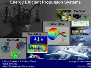
Review AE430Aircraft Propulsion Systems Gustaaf Jacobs
Note • Bring Anderson to exam for tables.
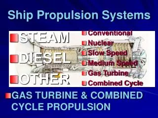
Goals • Understand and analyze gas turbine engines: • Turbojet • Turbofan (turbojet + fanned propeller)! • Ramjet
Analysis • Analysis • Energy control volume per engine component • Pressure and temperature changes for ideal engine • With efficiency definitions: pressure and temperature changes for non-ideal engine • Control Volume over complete engine: • Momentum balance=> thrust, propulsion efficiency • Energy balance or thermo analysis: • Brayton cycle: Thermal efficiency
Analysis • Detailed component analysis • Inlets • Subsonic flow analysis in 1D • Pressure recovery estimate • Shock analysis in 1D inlet (converging-diverging) • Estimate of losses • External deceleration principles • 2D shock external deceleration • Oblique shock analysis • Estimate spillage and losses
Analysis • Combustor • Qualitative idea of combustion physics • Fuel-air ratio (stoichiometric) • Flame speed • Flame holding • Quantitative: pressure loss with 1D channel flow analysis + heat addition=> not treated due to time restrictions • Compressor/Turbine • Estimate of pressure, temperature recovery with momentum and energy balance • Velocity triangles analysis: first order estimate of compressor aerodynamics
Engine PerformanceParameters • Propulsion efficiency, ratio thrust power to add kinetic energy • Thermal efficiency, ratio added kinetic energy to total energy consumption • Total efficiency • Thrust Specific Fuel Consumption
Thermodynamic cycles • Diagram that looks at the change of state variables at various stage of the engine • Ideal gas turbine: Brayton cycle • Isentropic compression, constant p heat addition, constant p heat rejection • First law of thermodynamics analysis gives expression for ηth
Ideal Ramjet • Analyze each stage using thermodynamic analysis with energy balance and isentropic relations to find: • P, T, p0, T0 • ve, T/ma • f
Ideal Ramjet • pt,0=pt,7, p0=p7 => M0=M7 • T7 > T0 since heat is added during combustion, so v7>v0 => Thrust • Fuel to air ratio, use first law:
Non-ideal ramjet • Non-isentropic compression and expansion: losses lead to lowered total pressure and temperature • Define total pressure ratios before and after components to quantify the efficiency: • rc, rn,rd
Non-Ideal turbojet • Major difference with ramjet ptotal is not constant like in ramjet but increases and decrease in compressor and turbine. • To find these ratios work from front to back through each stage • Specific: compressor and turbine power are the same so (first law)
Definition of component efficiencies • E.g. diffuser • Relates actual total temperature increase to an isentropic temperature increase • The isentropic temperature can be related to the total pressure using isentropic relations • The total pressure distribution is determined from front to back. • Each stage has an effiiciency like this.
Turbofan • Example on blackboard.
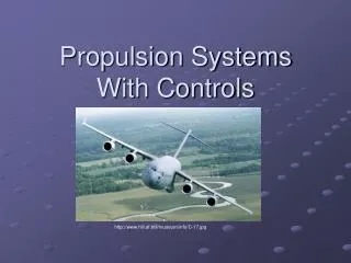
Intakes • Convert kinetic energy to pressure • Subsonic • External acceleration or decelleration depends on intake design and speed of aircraft • High speed: spillage. Low speed: stall. • Diffuser design: prevent stall: use computational (XFOIL, MSES) and experimental validation to design
Supersonic intake • 1D: converging-diverging nozzle • Ideal: isentropic decelleration supersonic to throat, subsonic after throat • Not possible in practice • Shocks in nozzle • Possible design: shock close to throat and M~1 at throat • Need overspeeding to swallow shock in throat. • Kantrowitz-Donaldson: design condition is shock swallowing condition.
Supersonic diffuser • 2-D nozzle • Use multiple oblique shocks to slow flow down with small losses in total pressure • Use oblique shock analysis
Combustor + Compressor • Discussed in last classes