Download
1 / 297
2.98k likes | 3.01k Views
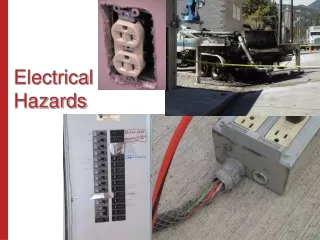
Electrical Hazards. Dr. Raed Al-Zubi University of Jordan. CHAPTER 1. ANALYSIS OF ELECTRICAL HAZARDS. Analysis of Electrical Hazards. Main types of electrical hazards: Shock Arc Blast. SHOCK.

E N D
Electrical Hazards Dr. Raed Al-Zubi University of Jordan
CHAPTER 1 ANALYSIS OF ELECTRICAL HAZARDS Dr. Raed Al-Zubi, The University of Jordan
Analysis of Electrical Hazards • Main types of electrical hazards: • Shock • Arc • Blast Dr. Raed Al-Zubi, The University of Jordan
SHOCK • Definition: Electric shock is the physical stimulation that occurs when electric current flows through the human body. • The final trauma associated with the electric shock is usually determined by the most critical path called the shock circuit. • The symptoms: may include a mild tingling sensation, violent muscle contractions, heart arrhythmia, or tissue damage. Dr. Raed Al-Zubi, The University of Jordan
SHOCK • Tissue damage may be attributed to at least two major causes: • Burning: Burns caused by electric current are almost always third-degree because the burning occurs from the inside of the body. • Cell Wall Damage: cell death can result from the enlargement of cellular pores due to high-intensity electric fields. This trauma called electroporation allows ions to flow freely through the cell membranes, causing cell death. Dr. Raed Al-Zubi, The University of Jordan
SHOCK • Influencing Factors: • Physical Condition and Physical Response. • Current Duration. • The amount of heat (energy) that is delivered is directly proportional to the duration of the current. • Tissue burning and/or organ shutdown can occur • Nervous system damage can be fatal even with relatively short durations of current. • longer duration of current through the heart is more likely to cause ventricular fibrillation. Dr. Raed Al-Zubi, The University of Jordan
SHOCK • Frequency: at higher frequencies, the effects of Joule heating become less significant. Victims of DC shock have indicated that they feel greater heating from DC than from AC. • Voltage Magnitude: higher voltages can be more lethal. At voltages above 400 V the electrical pressure may be sufficient to puncture the epidermis. • Current Magnitude: Dr. Raed Al-Zubi, The University of Jordan
SHOCK The current flow of 21.1 mA is sufficient to cause the worker to go into an “electrical hold.” This is a condition wherein the muscles are contracted and held by the passage of the electric current—the worker cannot let go. Under these circumstances, the electric shock would continue until the current was interrupted or until someone intervened and freed the worker from the contact. Unless the worker is freed quickly, tissue and material heating will cause the resistances to drop, resulting in an increase in the current. Such cases are frequently fatal. Dr. Raed Al-Zubi, The University of Jordan
SHOCK • Parts of the Body: Current flow affects the various bodily organs in different manners. For example, the heart can be caused to fibrillate with as little as 75 mA. The diaphragm and the breathing system can be paralyzed, which possibly may be fatal without outside intervention, with less than 30 mA of current flow. Dr. Raed Al-Zubi, The University of Jordan
ARC • Electric arcing occurs when a substantial amount of electric current flows through what previously had been air. Since air is a poor conductor, most of the current flow is actually occurring through the vapor of the arc terminal material and the ionized particles of air. This mixture of super-heated, ionized materials, through which the arc current flows, is called a plasma. Dr. Raed Al-Zubi, The University of Jordan
ARC • Arcs can be initiated in several ways: • When the voltage between two points exceeds the dielectric strength of the air. This can happen when over-voltages due to lightning strikes. • When the air becomes superheated with the passage of current through some conductor. For example, if a very fine wire is subjected to excessive current, the wire will melt, superheating the air and causing an arc to start. Dr. Raed Al-Zubi, The University of Jordan
ARC Dr. Raed Al-Zubi, The University of Jordan
ARC • Electric arcs are extremely hot. Temperatures at the terminal points of the arcs can reach as high as 50,000 kelvin (K). • The heat energy of an electrical arc can kill and injure personnel at surprisingly large distances. For example, second-degree burns have been caused on exposed skin at distances of up to 12 feet (ft) or (3.6 meters [m]) and more. • All types of clothing fibers can be ignited by the temperatures of electrical arcs. Dr. Raed Al-Zubi, The University of Jordan
ARC • Arc Energy Release • Arc energy is released in at least three forms—light, heat, and mechanical (Flying objects). • Arc Energy Input • The energy supplied to an electric arc by the electrical system, called the arc input energy may be calculated using the formula where θ = the angle between current and voltage Dr. Raed Al-Zubi, The University of Jordan
ARC • Arcing Current • Equation 1.7 is the formula used for electrical arcs in systems with voltages less than 1000 V and Eq. 1.8 is used for systems with voltages equal to or greater than 1000 V. (IEEE Standard Std 1584-2002) Dr. Raed Al-Zubi, The University of Jordan
ARC ● Three-phase voltages in the range of 208 to 15,000 V phase-to-phase ● Frequencies of 50 or 60 Hz ● Fault current in the range of 700 to 106,000 A ● Gaps between conductors of 13 to 152 mm Dr. Raed Al-Zubi, The University of Jordan
ARC • Arcing Voltage • Arc voltage is somewhat more difficult to determine. Values used in power system protection calculations vary from highs of 214.4 V/m to as low as 91.4 V/m. Dr. Raed Al-Zubi, The University of Jordan
ARC • Arc Surface Area Dr. Raed Al-Zubi, The University of Jordan
ARC • Incident Energy • It is the energy transfer from the arc to the nearby body • One of the methods proposed to calculate incident energy: E = incident energy in J/cm2 V = system voltage (phase-to-phase) t = arcing time (seconds) D = distance from arc point to person or object (mm) Ibf = bolted fault current (kA) Dr. Raed Al-Zubi, The University of Jordan
ARC • Arc Burns • First-degree burns. First-degree burning causes painful trauma to the outer layers of the skin. Little permanent damage results from a first-degree burn because all the growth areas survive. Healing is usually prompt and leaves no scarring. • Second-degree burns. Second-degree burns result in relatively severe tissue damage and blistering. If the burn is to the skin, the entire outer layer will be destroyed. Healing occurs from the sweat glands and/or hair follicles. • Third-degree burns. Third-degree burns to the skin result in complete destruction of the growth centers. If the burn is small, healing may occur from the edges of the damaged area; however, extensive third-degree burns require skin grafting. Dr. Raed Al-Zubi, The University of Jordan
BLAST • When an electric arc occurs, it superheats the air instantaneously. This causes a rapid expansion of the air with a wavefront that can reach pressures of 100 to 200 lb per square foot. Dr. Raed Al-Zubi, The University of Jordan
BLAST Dr. Raed Al-Zubi, The University of Jordan
CHAPTER 2 ELECTRICAL SAFETY EQUIPMENT Dr. Raed Al-Zubi, The University of Jordan
SAFETY EQUIPMENTS • Always perform a detailed inspection of any piece of electrical safety equipment before it is used. Such an inspection should occur at a minimum immediately prior to the beginning of each work shift, and should be repeated any time the equipment has had a chance to be damaged Dr. Raed Al-Zubi, The University of Jordan
SAFETY EQUIPMENTS • Flash and Thermal Protection • Head and Eye Protection • Rubber-Insulating Equipment • Hot Sticks • Insulated Tools • Barriers and Signs • Safety Tags, Locks, and Locking Devices • Voltage-Measuring Instruments • Safety Grounding Equipment • Ground Fault Circuit Interrupters Dr. Raed Al-Zubi, The University of Jordan
Flash and Thermal Protection • Fire protection equipment has slightly different requirements and is not covered • The extremely high temperatures and heat content of an electric arc can cause extremely painful and/or lethal burns Dr. Raed Al-Zubi, The University of Jordan
Flash and Thermal Protection Dr. Raed Al-Zubi, The University of Jordan
Flash and Thermal Protection • Workers must wear thermal protective clothing with an Arc Thermal Performance Value (ATPV) equal to or greater than the amount of incident arc energy to which they might be exposed • The ATPV for any given material is calculated using the procedures defined in ASTM Standard F 1959/F 1959M Dr. Raed Al-Zubi, The University of Jordan
Flash and Thermal Protection • Arc Thermal Performance Value (ATPV). Research by Stoll & Chianta developed a curve (the so-called Stoll curve) for human tolerance to heat. The curve is based on the minimum incident heat energy (in kJ/m2 or cal/cm2) that will cause a second-degree burn on human skin. Modern standards that define the level of thermal protection required are based on the Stoll curve. That is, clothing must be worn that will limit the degree of injury to a second-degree burn. This rating is called the Arc Thermal Performance Value (ATPV). Dr. Raed Al-Zubi, The University of Jordan
Flash and Thermal Protection • ASTM Standards. The American Society of Testing and Materials (ASTM) has three standards that apply to the thermal protective clothing to be worn by electrical workers Dr. Raed Al-Zubi, The University of Jordan
Flash and Thermal Protection Dr. Raed Al-Zubi, The University of Jordan
Flash and Thermal Protection • Other Standards. The principal standards for electrical worker thermal protection are OSHA 1910.269 and ANSI/NFPA 70E. Of these two, 70E is the most rigorous and provides the best level of protection, and it defines user thermal protection requirements on the basis of the ATPV. Dr. Raed Al-Zubi, The University of Jordan
Flash and Thermal Protection • Clothing Materials 1. Non-flame-resistant materials. When these materials are treated with a flame-retardant chemical, they become flame resistant. a. Natural fibers such as cotton and wool (do not melt into skin) b. Synthetic fibers such as polyester, nylon, and rayon (They melt into skin) Dr. Raed Al-Zubi, The University of Jordan
Flash and Thermal Protection 2. Flame-resistant materials a. Non-flame-resistant materials that have been chemically treated to be made flame-resistant b. Inherently flame-resistant materials such as PBI, Kermel, and Nomex Flame-retardant cotton, flame-retardant synthetic cotton blend, NOMEX, PBI, or other flame-retardant materials are preferred Dr. Raed Al-Zubi, The University of Jordan
Flash and Thermal Protection • Flash Suits • The suit should be selected with an ATPV sufficient for the maximum incident energy that may be created in the work area • A flash suit is a thermal-protective garment made of a heavier-weight NOMEX, PBI, or other flame resistant material. Dr. Raed Al-Zubi, The University of Jordan
Flash and Thermal Protection Dr. Raed Al-Zubi, The University of Jordan
HEAD AND EYE PROTECTION • Hard Hats • Such hats should comply with the latest revision of the American National Standards Institute (ANSI) standard Z89.1 which classifies hard hats into three basic classes: 1. Class G hard hats are intended to reduce the force of impact of falling objects and to reduce the danger of contact with exposed low-voltage conductors. They are proof tested by the manufacturer at 2200 V phase-to-ground 2. Class E hard hats are intended to reduce the force of impact of falling objects and to reduce the danger of contact with exposed high-voltage conductors. They are proof tested by the manufacturer at 20,000 V phase-to-ground 3. Class C hard hats are intended to reduce the force of impact of falling objects. They offer no electrical protection. Dr. Raed Al-Zubi, The University of Jordan
HEAD AND EYE PROTECTION Dr. Raed Al-Zubi, The University of Jordan
HEAD AND EYE PROTECTION • Safety Glasses, Goggles, and Face Shields • The plasma cloud and molten metal created by an electric arc are projected at high velocity by the blast. If the plasma or molten metal enters the eyes, the extremely high temperature will cause injury and possibly permanent blindness • Protection should comply with the latest revision of ANSI standard Z87.1 • Goggles which reduce the ultraviolet light intensity are also recommended Dr. Raed Al-Zubi, The University of Jordan
HEAD AND EYE PROTECTION Dr. Raed Al-Zubi, The University of Jordan
RUBBER-INSULATING EQUIPMENT • Rubber-insulating equipment includes rubber gloves, sleeves, line hose, blankets, covers, and mats • The American Society of Testing and Materials (ASTM) publishes recognized industry standards which cover rubber insulating goods Dr. Raed Al-Zubi, The University of Jordan
RUBBER-INSULATING EQUIPMENT • Rubber Gloves: A complete rubber glove assembly is composed of a minimum of two parts: the rubber glove itself and a leather protective glove • The ASTM publishes four standards which affect the construction and use of rubber gloves: 1. Standard D 120 establishes manufacturing and technical requirements for the rubber glove. 2. Standard F 696 establishes manufacturing and technical requirements for the leather protectors. 3. Standard F 496 specifies in-service care requirements. 4. Standard F 1236 is a guide for the visual inspection of gloves, sleeves, and other such rubber insulating equipment. Dr. Raed Al-Zubi, The University of Jordan
RUBBER-INSULATING EQUIPMENT • Rubber gloves are available in six basic voltage classes from class 00 to class 4, and two different types: types I (not ozone-resistant) and II (ozone-resistant) Dr. Raed Al-Zubi, The University of Jordan
RUBBER-INSULATING EQUIPMENT • Rubber gloves should be thoroughly inspected and air-tested before each use. They may be lightly dusted inside with talcum powder or manufacturer supplied powder. This dusting helps to absorb perspiration and eases putting them on and removing them. • Caution: Do not use baby powder on rubber gloves. Cotton inserts are highly recommended for worker comfort and convenience • Always check the last test date marked on the glove and do not use it if the last test was more than 6 months earlier than the present date. Dr. Raed Al-Zubi, The University of Jordan
RUBBER-INSULATING EQUIPMENT • Rubber Mats: are used to cover and insulate floors for personnel protection. Rubber insulating mats should not be confused with the rubber matting used to help prevent slips and falls • The ASTM standard D-178 specifies the design, construction, and testing requirements for rubber matting • ASTM D-178 must also appear on the mat. This marking is to be placed a minimum of every 3 ft (1 m). Dr. Raed Al-Zubi, The University of Jordan
RUBBER-INSULATING EQUIPMENT Dr. Raed Al-Zubi, The University of Jordan