Download
1 / 46
470 likes | 637 Views
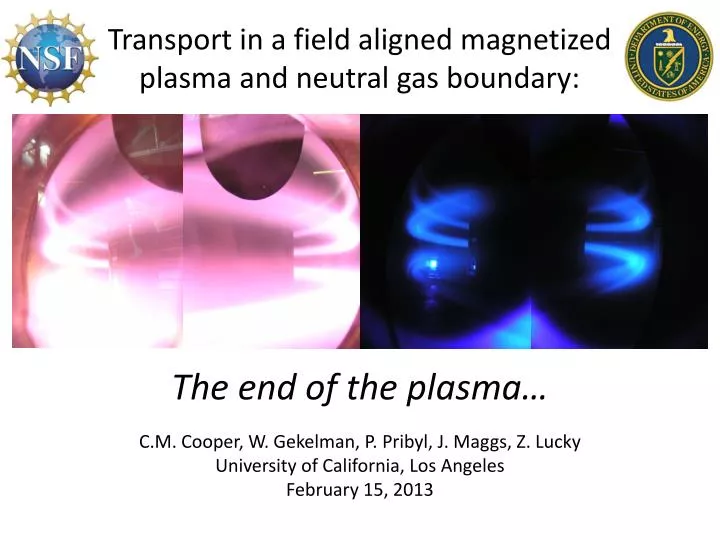
Transport in a field aligned magnetized plasma and neutral gas boundary:. The end of the plasma… C.M. Cooper, W. Gekelman , P. Pribyl , J. Maggs , Z. Lucky University of California, Los Angeles February 15, 2013. Overview. Motivation Relation to Auroral Physics, Divertor Physics

E N D
Transport in a field aligned magnetized plasma and neutral gas boundary: The end of the plasma… C.M. Cooper, W. Gekelman, P. Pribyl, J. Maggs, Z. Lucky University of California, Los Angeles February 15, 2013
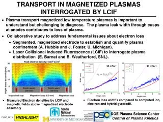
Overview • Motivation • Relation to Auroral Physics, Divertor Physics • Summary of Enormous Toroidal Plasma Device • Model of ETPD plasma regions • Neutral Boundary Layermodel: Plasma Termination • Occurs at plasma/neutral gas pressure equilibrium • Plasma terminates on current-free ambipolar sheath determined by a generalized Ohm’s law • Heating, ionization occur in NBL • Measured scaling lawsin ETPD
Motivation: Aurora The auroral-arc current loop associated with a perpendicular electric field imposed in the magnetosphere [Borovsky 1993] Aurora over Jokulsarlon Lake, Iceland Stephane Vetter, “Nuitssacrees” Feb. 2011 Schematic view of parallel currents j||, plasma motions, vperp, electric fields, and potential contours above auroral arc, sketched in green [Haerendel 1996] J. Borovsky, J. Geo Res 98, A4 6101-6138 (1993) G. Haerendel, J. Atmos. Terr. Phys. 58,1-4 71-83 (1996)
Motivation: Gaseous Divertors Gaseous divertor design for DIII-D Gaseous divertors designed to dissipate plasma particles, momentum, and energy on neutral gas before touching wall Gaseous divertor design for JET R. W. Conn, Fusion and Eng. Design 14 81-97 (1991)
Diagram of the ETPD Toroidal Magnets (red) provide a 250 G confining field Vertical Magnets (blue) provide a 6 G vertical field to space out rings LaB6 source injects primaries to form then heat the plasma ETPD Plasma (pink) follows the helical magnetic field up to 120 m C.M. Cooper et al, Rev of Sci Inst. 81 083503 (2010) R.J. Taylor et al, Nuclear Fusion 42 46-51 (2002)
Picture of a LaB6 Cathode Frame and Shielding Heater Anode Cathode
Experimental Setup • Primary electrons boiled off LaB6 are accelerated along the field by anode. • Primaries ionize neutral gas to create and heat plasma. • Data taken where plasma ends, 90% around machine.
Neutral Boundary Layer 400 V discharge 2 mTorr 300 V discharge 2.5 mTorr 220 V discharge 3.6 mTorr 2.2 kA Probe
Energy Balance in ETPD 220 V e e e e e Helium Gas e e e e e e e e e e e e e e e e e e e HEAT HEAT B Ionosphere HEAT HEAT HEAT HEAT HEAT HEAT HEAT HEAT HEAT HEAT HEAT HEAT e e e e e Atmo- sphere i i <100 kV i i i Energy Balance in Aurora e e e e e e
3 Zones in ETPD Plasma • Conduction/ ionization • - Radial diffusion • Ohmic Heating and cooling • - Ionization and Radial diffusion + Thermalization of primaries + ionization > losses Heat Density Take Data Efield Term. Energy loss length Energy input length
Ambipolar Termination Sheath in NBL! Plasma potential in neutral gas boundary indicative of large field-aligned electric field 1 0 -1 -2 -3 -4 40 20 0 -20 -40 Relative y coord (cm) -60 -40 -20 0 20 40 60 -40 -20 0 20 40 60 -40 -20 0 20 40 -40 -20 0 20 40 60 Fp(eV) Relative x coord (cm) Relative x coord (cm) Relative x coord (cm) Relative x coord (cm) Neutral fill of 3.6 mTorr He, a plasma discharge of 194 A 220 V, Btor=250 G, Bver=6 G,
GenerateRadial Profiles Used to study rate at which particles, momentum, and heat move across the field and out of the plasma 1 0 -1 -2 -3 -4 40 20 0 -20 -40 Relative y coord (cm) -60 -40 -20 0 20 40 60 -40 -20 0 20 40 60 -40 -20 0 20 40 -40 -20 0 20 40 60 Fp(eV) Relative x coord (cm) Relative x coord (cm) Relative x coord (cm) Relative x coord (cm) Neutral fill of 3.6 mTorr He, a plasma discharge of 194 A 220 V, Btor=250 G, Bver=6 G,
Generate Axial Profiles in NBL Plot data along the center of plasma coordinate “s” Three zones! ABC A B C 1 0 -1 -2 -3 -4 40 20 0 -20 -40 Relative y coord (cm) -60 -40 -20 0 20 40 60 -40 -20 0 20 40 60 -40 -20 0 20 40 -40 -20 0 20 40 60 Fp(eV) Relative x coord (cm) Relative x coord (cm) Relative x coord (cm) Relative x coord (cm) Neutral fill of 3.6 mTorr He, a plasma discharge of 194 A 220 V, Btor=250 G, Bver=6 G,
Neutral Boundary Layer Model • Three-fluid, current-free • Continuity equation: ionization and losses A • Momentum equation: pressure equilibration • Momentum equation: generalized Ohms Law B • Heat equation: ionization and Ohmic heating C
Zone A: Pressure Equilibration For • Diffusivity argument: Neutral density convected out along field by plasma, diffuses across field • Drag force limited to cross-field neutral diffusion rate / • Axial neutral flow develops from force balance Momentum gained from plasma = Momentum lost to stationary neutrals
Electron Temperature in Zone A -1 -2 -3 • Constant • Ionization ~ 0 Fp (eV) 3 2 Te (eV) 2400 2600 2800 3000 3200 Distance from anode (cm)
Plasma Velocity in Zone A -1 -2 -3 • Plasma velocity is flat • Momentum balance • Sets a critical velocity Fp (eV) 4 2 0 0.5 0.4 0.3 0.2 0.1 0 vp (105cm/s) Plasma mach at 2.2 eV 2400 2600 2800 3000 3200 Distance from anode (cm)
Plasma Density in Zone A -1 -2 -3 • Plasma density is dropping from radial losses Fp (eV) 1.2 0.8 0.4 ne (1012/cm3) 2400 2600 2800 3000 3200 Distance from anode (cm)
Zone B: Ambipolar Electric Field i i i i i i i i i i i i i i i i Current-free plasma sees neutral gas at end e e e e e e e e e e Electrons stop, ion current penetrates e e Electric field develops, drives electron current i e Electric field maintains Current free term. e e e e i
Potential Structure in NBL • Plasma iso-potentials form “nested V’s” • White arrows show electric field, parallel field 10x • Quasineutral lei len lD Colormap of plasma potential from 1,300 points interpolated onto toroidal coordinates
Electron Temperature in Zone B -1 -2 -3 • Electron temperature rises with potential • For Fp (eV) Fp 3 2 Te (eV) 2400 2600 2800 3000 3200 Distance from anode (cm)
Plasma Velocity in Zone B -1 -2 -3 • Plasma velocity drops due to drag on neutrals Fp (eV) 4 2 0 0.5 0.4 0.3 0.2 0.1 0 vp (105cm/s) Plasma mach at 2.2 eV 2400 2600 2800 3000 3200 Distance from anode (cm)
The difference between momentum and temperature loss Electrons • Momentum loss: – faster • Energy loss: – slower In electric field, electrons HEAT. • Ions • Momentum loss: • – slower • Energy loss: • – faster In electric field, ions SLOW.
Plasma Density in Zone B -1 -2 -3 • Plasma density is dropping from radial losses • Balance between Flux conservation • Adiabatic heating Fp (eV) 1.2 0.8 0.4 ne (1012/cm3) 2400 2600 2800 3000 3200 Distance from anode (cm)
Plasma Termination Use generalized Ohms law to solve for electric field
Zone C: Additional Ionization R. K. Janev, Elementary Processes in Hydrogen and Helium Plasmas (1987)
Electron Temperature in Zone C -1 -2 -3 • Prediction: Electron temperature continues to rise rapidly with potential Fp (eV) 3 2 Te (eV) 2400 2600 2800 3000 3200 Distance from anode (cm)
Electron Temperature in Zone C -1 -2 -3 IONIZATION Fp (eV) 3 2 Te (eV) 2400 2600 2800 3000 3200 Distance from anode (cm)
Plasma Density in Zone C -1 -2 -3 • Prediction: Plasma density continues to drop Fp (eV) 1.2 0.8 0.4 ne (1012/cm3) 2400 2600 2800 3000 3200 Distance from anode (cm)
Plasma Density in Zone C -1 -2 -3 IONIZATION Fp (eV) 1.2 0.8 0.4 ne 10% (1012/cm3) 2400 2600 2800 3000 3200 Distance from anode (cm)
Plasma Production in Boundary If all energy gained went into plasma production how much could you make? For What’s the mean free path of ionization? Any energy gained by electric field is quickly absorbed by ionization
Plasma Velocity in Zone C -1 -2 -3 • Prediction: Plasma velocity will drop to 0 Fp (eV) 4 2 0 0.5 0.4 0.3 0.2 0.1 0 vp (105cm/s) Plasma mach at 2.2 eV 2400 2600 2800 3000 3200 Distance from anode (cm)
Plasma Velocity in Zone C -1 -2 -3 • Additional flux is generated by the ionization at the end of the plasma • Still slowing down after ionization ends IONIZATION Fp (eV) 4 2 0 0.5 0.4 0.3 0.2 0.1 0 vp (105cm/s) Plasma mach at 2.2 eV 2400 2600 2800 3000 3200 Distance from anode (cm)
NBL Conserved Quatities Axial Plasma Flux: Normalized Plasma Pressure: 4 2 0 1.4 1.0 0.6 Gp,s=npvp,s Pp=(np(Ti+Te)/(nnTn)) • Plasma flux: • Measure of axial particle flux • Only loss of axial flux is radial flux • Filling in of profile • Kinetic effects (trapped particles) • Normalized Plasma Pressure: • End of the plasma occurs where pp=pn • Dropping pressure “interrupted” by termination E field 2400 2600 2800 3000 3200 2400 2600 2800 3000 3200 Distance from anode (cm) Distance from anode (cm)
Scaling of Ambipolar Electric Field The potential marks a “footprint” for the boundary of the plasma 49 kW 43 kW 39 kW The location and magnitude of Electric field terminating the plasma change as a function of input power Measure plasma parameters
Scaled Plasma Parameters pre-NBL (a) • Axial flow drops • Te is flatat 2.2 eV (b) • Extra power raises density (c)
Scaling Study pp=pn seq,m=seq,t Es,m=Es,t Measured electric field, Es,m, scales like the theoretical ambipolar value Measured termination point, seq,m, coincides with location of pressure equilibration
Modified Ambipolar Flow in ETPD Electron current Ion current Electron current Ion current Ion current Electron current
Ambipolar Flow in NBL • Magnetic field data from probe indicates axial current • Negative current carried by electrons moving in positive direction Data taken at s = 2870 cm, halfway through NBL
Non-Zero Current in NBL • NBL not current free • Current trends to zero • Drift speed associated with current << bulk flow
Types of Current Some currents diverge and need to be closed to maintain J=0 Note: Steady state so Jpolz = 0 Divergence-Free Non Divergence-Free Some currents are associated with particle drifts and transport • Parallel (e-n) Current • Radial Pederson (i-n) Current • Vertical/B Currents • Poloidal Hall (i-n) Current (+) Transport Causing • Poloidal Diamagnetic Current (-) Non Transport Causing
Estimation of Jr Jr • Axial current tied to Radial current JS Ar JSo+DS = JSo + Jr AS Kirchoff’s Junction Rule
Future Work on NBL • Observational • Measure plasma potential and flows in Aurora • Experimental • Study NBL for different pressures and/or gases • Simulation • Model in DEGAS (neutral gas collisional code)* • Model in UEDGE (transport code)* • RungeKutta solver for fluid model**
Future work: 1.5-D Simulation Measured 5 things: Model neutral gas Solve 5 equations + neutral gas transport: Generalized Source/Sink calibrated by data
Conclusions • Plasma terminates on ambipolar electric field • Electric field occurs where diminishing plasma pressure and neutral pressure equilibrate • NBL dominated by termination field through Ohmic heating and ionization • NBL has a small modified ambipolar diffusion due to differences in directional particle motilities