Download
1 / 21
240 likes | 547 Views
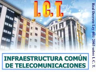
I.C.T. INFRAESTRUCTURA COMÚN DE TELECOMUNICACIONES. I. C. T. Real Decreto Ley 401/ 2003 sobre I. C. T. INFRAESTRUCTURA COMÚN DE TELECOMUNICACIONES. ¿QUÉ ES UNA I.C.T.?.

E N D
I.C.T. INFRAESTRUCTURA COMÚN DE TELECOMUNICACIONES I. C. T. Real Decreto Ley 401/ 2003 sobre I. C. T. INFRAESTRUCTURA COMÚN DE TELECOMUNICACIONES
¿QUÉ ES UNA I.C.T.? Conjunto de sistemas de captación y adaptación de señales radioeléctricas y telefónicas, para su distribución en viviendas y locales comerciales. PARTES DE LA INFRAESTRUCTURA: Recintos, canalizaciones y mecanismos. Dispositivos de captación de señales. Equipos de tratamiento de señal. Elementos de distribución.
INTRODUCCIÓN: El 22-2-99, se dictó el Real Decreto 279/1999 para aprobar el Reglamento regulador de las I.C.T. “Insfraestructuras Comunes de Telecomunicaciones” Después de 4 años necesitaba actualizarse a las nuevas tecnologías de telecomunicación, y eso pretende el Real Decreto 401/2003 de 4 de Abril. Desde el día siguiente a su publicación en el B.O.E. entró en vigor, quedando anulado el R.D. 279/1999.
¿CUÁL ES SU OBJETIVO? Garantizar el derecho de los ciudadanos al acceso a los nuevos servicios de Telecomunicaciones. Establecer la normativa y especificaciones técnicas de telecomunicación relativa a la infraestructura de acceso a estos servicios. Determinar las condiciones y medios técnicos del instalador de telecomunicaciones, para garantizar las instalaciones y su puesta en servicio.
¿DÓNDE SE APLICARÁ? A todos los edificios y conjuntos inmobiliarios y sean o no de nueva construcción, acogidos al régimen de propiedad horizontal (RD 49-1960 de 21 de Julio y 8-1999 de 6 de Abril). A los edificios que, en todo o en parte, hayan sido arrendados por más de un año, salvo los de una sola vivienda.
Televisión por cable:TLCA y Servicios de Banda Ancha: SAFI. (Anexo III ) Televisión terrestre y satélite:TVT-SAT.(Anexo I ) Telefonía Básica, RDSI, ADSL, etc. (Anexo II ) ¿QUÉ SERVICIOS OFRECE?
HABRÁ TRES REGISTROS DE TOMA, UNO PARA CADA SERVICIO: TB+RDSI, TLCA Y SAFI, Y RTV. EN AQUELLAS ESTANCIAS, EXCLUIDOS BAÑOS Y TRASTEROS, EN LAS QUE NO SE INSTALE TOMA, EXISTIRÁ UN REGISTRO DE TOMA, NO ASIGNADO ESPECÍFICAMENTE A UN SERVICIO CONCRETO. LOS REGISTROS DE TOMA TENDRÁN CERCA (MÁXIMO 500 mm) UNA TOMA DE CORRIENTE ALTERNA. EJEMPLO DE INSTALACIÓN MÍNIMA
Nº ESTANCIAS/2+0’5 EXCLUIDOS BAÑOS -TRASTEROS NÚMERO DE TOMAS por servicio y USUARIO SÓLO SI HAY FRACCIÓN 1 x TLCA-SAFI 1 x TVT-SAT 1 x TB-RDSI-ADSL Nº ESTANCIAS 2 + 0’5 EXCLUIDOS BAÑOS Y TRASTEROS CON UN MÍNIMO DE DOS TOMAS TENDRÁN UNA TOMA DE CORRIENTE A MENOS DE 50 cm
DISTRIBUCIÓN DE LA INSTALACIÓN-ESQUEMA RECINTO DE INSTALAC. DE TELECOM. SUPERIOR ANTENAS REGISTRO SECUNDARIO PUNTO DE ACCESO USUARIO - PAU y R.T.R. TELEF. BÁSICA-RDSI +TV POR CABLE+SAFI +TV TERRESTRE Y SATÉLITE TB TVC TV A TOMAS USUARIO REGISTRO DE ENLACE ARQUETA EXTERIOR RECINTO DE INSTALAC. DE TELECOM. INFERIOR DISTRIBUCIÓN DE LA INSTALACIÓN
CANALIZACIONES-DIÁMETRO TUBOS ANTENAS R I T S 5X50 5.7.1 4X40 5.4.2 3X25 5.9 5X50 5.7.1 TB TVC TV 3X63 5.2 ARQUETA EXTERIOR 3X40 5.4 R I T I REGISTRO DE ENLACE CANALIZACIONES Nº Y DIÁMETRO DE TUBOS 1X20 5.12
APÉNDICE 1 – ESQUEMA GENERAL, NOMENCLATURAS ESQUEMA EXTRAÍDO DEL REGLAMENTO
MEDIDA RECINTOS Y REGISTROS-ESQUEMA ANTENAS R I T S MODULAR 2X1X0’5 m 5.5.1 1x2x0’5 m RS TB 10X17X4 cm TVC 20X30X4 cm TV 20x30x6 cm 5.11 TB TVC TV 45X45X15 cm 5.8 45X45X12 cm 5.4.1 MODULAR ARQUETA EXTERIOR 40X40X60 5.1 1x2x0’5 m 2X1X0’5 m 5.5.1 R I T I REGISTRO DE ENLACE PAU MEDIDA DE RECINTOS Y REGISTRO
APÉNDICE 2 - CANALIZACIONES ESQUEMA EXTRAÍDO DEL REGLAMENTO
ARQUETA DE ENTRADA ENTRADA EXTERIOR REPORTAJE GRÁFICO
RECINTO DE ENTRADA R.I.T.I.
DERIVADORES TV-SAT REGLETAS DE PARES TELEFÓNICOS DERIVADORES PARA TVT Y SAT 13
PUNTO ACCESO USUARIOREGISTRO TERMINACIÓN DE RED TV POR CABLE TVT-SAT TELEFONÍA PAU - RTR PUNTO DE ACCESO USUARIO REGISTRO TERMINACIÓN DE RED 14
TOMAS DE USUARIO CONTROL DE LA SEÑAL EN LA TOMA DE USUARIO HUECO DE RESERVA TOMA SAT-FI TOMA TV+FM 15
RECINTO SUPERIOR EQUIPO AMPLIFICACIÓN TVT AMPLICADOR DE F I RECINTO SUPERIOR 16
SISTEMA DE CAPTACIÓN ACCESO A LOS EQUIPOS DE CAPTACIÓN DETALLE DE LA CONEXIÓN A TIERRA DE LAS MASAS METÁLICAS 17