Download
1 / 7
70 likes | 168 Views
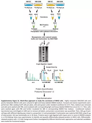
T-lines to MCP coupling. Jean-Francois Genat March 17 th 2009. Copper plate. Paper. T-line card. Dummy MCP plate. 2” x 2” copper plate on top of T-line 100-400 m m of paper in between. Transmission, Reflection modes. Transmission mode: edge propagation (timing) Pulse r Ch1

E N D
T-lines to MCP coupling Jean-Francois Genat March 17th 2009
Copper plate Paper T-line card Dummy MCP plate 2” x 2” copper plate on top of T-line 100-400 mm of paper in between
Transmission, Reflection modes • Transmission mode: edge propagation (timing) Pulser Ch1 • Reflection mode: reflections (double pulse resolution in sampling mode) Scope TDS 6154C Scope TDS 6154C Pulser Ch1 50W
Fast pulse to T-line card Reflection mode with and without MCP • With MCP - Measured reflection: 17% - Impedance mismatch: 50W x (1-.17)/(1+.17) = 35.5W • Without MCP - No measurable reflection: T-line is 50W
Measurements. Bare T-line card Transmission mode
Measurements. Bare T-line card Reflection mode
Conclusions: T-line + electrode Impedance Therefore: A minimum width of 175mm is required for the MCP second gap to control the T-line impedance within 10%