Download
1 / 18
180 likes | 184 Views
The D etector S afety S ystem for LHC Experiments. Stefan.Lueders@cern.ch (EP/DI & IT/CO) The DSS Team 3 rd JCOP Workshop, June 5 th 2002. O verview. DSS Overview Experiment Safety The JCOP DSS Project The DSS Functional Requirements Experiment Needs Design and Architecture

E N D
The Detector Safety Systemfor LHC Experiments Stefan.Lueders@cern.ch (EP/DI & IT/CO) The DSS Team 3rd JCOP Workshop, June 5th 2002
Overview • DSS Overview • Experiment Safety • The JCOP DSS Project • The DSS • Functional Requirements • Experiment Needs • Design and Architecture • Conclusions and Outlook ”The DSS for LHC Experiments” by Stefan Lüders
hardwired information information via network action signal DIP(LDIWG) CSS CSAM, CSE, etc. DCS Infrastr.Control Infrastr.Control Sub-Detector Sub-Detector Tracker Tracker Temp Smoke,Gas Leak,etc. Services (Power, Water, Gas) Experiment (Sub-Detector, Racks, Gas) CERN Safety System safety system including the CERN Safety Equipment with its own sensors and the CERN Safety Alarms and Monitoring system with its information links All required Safety Actions (in case of a Level 3 Alarm) are handled by CSS Detector Control System software controls system running PVSS on the supervisory and the sub-system layersall PVSS systems are interconnected via network Technical Services Technical Services DIP(LDIWG) CSS CSAM, CSE, etc. DCS Supervisory Layer (PVSS) Data Interchange network connection running the Data Interchange Protocol defined by the LDIWG Technical Services entity including all provided services like power, water, gas; this bubble references their respective controls systems Infrastr.Control Sub-System Layer (PVSS) Equipment equipment that is acted upon by CSS, DSS, and/or DCS, e. g. power distribution, (sub-)detectors, racks, magnet, gas systems Temp Smoke,Gas Leak,etc. Services (Power, Water, …) Experiment (Sub-Detector, Racks, Gas) Infrastructure Controls System sub-system of the DCS that handles infrastructure and environment controls, e.g. racks, together with its own sensors ”The DSS for LHC Experiments” by Stefan Lüders
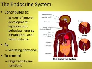
Experiment Safety • Safety for personnel is ensured by the CSS. • The DCS is responsible for the overall monitoring and control of the detector. It might initiate corrective action to maintain normal operation. • The DSS complements CSS and DCS: “The DSS is a system to safeguard the experiment. As such, it acts to prevent damage to the experimental equipment when a serious fault situation is detected (e.g. temperature too high, water leak…), inside or outside of the detector…” ”The DSS for LHC Experiments” by Stefan Lüders
Scope and Goal:An Optimization Challenge The DSS should… • protect experimental equipment • improve the experiment’s efficiency by • preventing situations leading to severe (CSS) alarms • decreasing downtimes due to failures • not cost too much • consider it like an insurance policy ”The DSS for LHC Experiments” by Stefan Lüders
Constraints for DSS • easy integration • into the controls system of the experiment • of sub-detector safety systems • of subsystems (racks, gas, magnets, …) • adaptability • to different needs of the four experiments • to evolving experimental environments • maintainability ”The DSS for LHC Experiments” by Stefan Lüders
hardwired information information via network action signal DIP(LDIWG) CSS CSAM, CSE, etc. DCS DSS Infrastr.Control Infrastr.Control Sub-Detector Sub-Detector Tracker Tracker DSSFront-End Front-End Layer (PLC, …) Temp Temp,Humidity,Status, etc. Smoke,Gas Leak,etc. Services (Power, Water, Gas) Experiment (Sub-Detector, Racks, Gas) Technical Services Technical Services DIP(LDIWG) CSS CSAM, CSE, etc. DCS Supervisory Layer (PVSS) Infrastr.Control Sub-System Layer (PVSS) • Detector Safety System • system consisting of • a supervisory part (back-end), which is in-turn a subsystem of the DCS, and • a front-end part consisting of independent • Detector Safety Units(based on PLCs, plus own sensors) hardwired information exchange between CSS and DSS front-end CSSDSS Front-End: information about level 2 or 3 alarms DSS Front-EndCSS: information about an alarm condition Temp Smoke,Gas Leak,etc. Services (Power, Water, …) Experiment (Sub-Detector, Racks, Gas) ”The DSS for LHC Experiments” by Stefan Lüders
ALICE JCOP feedback ATLAS advises proposes CMS LHC-b The DSS Project DSS Team IT/CO & EP Advisory Board Bruce Flockhart (project leader) Giulio Morpurgo (developer) Sascha Schmeling (safety systems expert) Stefan Lüders (developer) • Wayne Salter (chairman) • experiments’ representatives • external experts (CSS, GSS, …) • standard JCOP subproject ”The DSS for LHC Experiments” by Stefan Lüders
The DSS Functional Requirements The DSS Front-End… • will have its own sensors and power sources • will be based on PLC technology • will check and filter the sensor inputs • will react immediately and always autonomously on fault conditions indicated by the sensors The DSS User Interface (Back-End) will… • be based on the JCOP framework and PVSS • monitor and control the Front-End • allow an easy definition of the input parameters and the actions performed in case of failures through controlled access (the “Alarm/Action Matrix”) • displays / logs alarm states, warnings and related info The DSS functional requirements are described in CERN-JCOP-2002-012: http://itcowww.cern.ch/DSS/StG/Minutes/25-04-02/DSSFRD_20020425.pdf “A Detector Safety System for the LHC Experiments” chaired by Philippe Gavillet The DSS is a standalone system and must be… • highly reliable • highly available • as simple and robust as possible • rapidly re-configurable by experts • self-checking for consistency ”The DSS for LHC Experiments” by Stefan Lüders
PLC: cycle time T>Tthres T>Tthres AND Alarm T>Tthres Sensors Output: Action (e.g. switching off power) The Alarm/Action Matrix The PLC loop: • PLCs continuously monitor the inputs • e.g. temperatures, water / gas flows, gas sniffer status • input parameters are compared to programmable thresholds • several conditions can be logically combined. Their fulfillment produces an alarm End-of-loop • alarms evoke defined actions • actions are on a coarse level (e.g. cutting power for rack rows) ”The DSS for LHC Experiments” by Stefan Lüders
Experiments Needs • 200 to 800 inputs to be monitored • sensors located in several buildings (caverns & surface) • less outputs Geographicallydistributed system ”The DSS for LHC Experiments” by Stefan Lüders
Sensors Outputs (e.g. power switch) DSS Overview • Input / Output • local I/O interfaces near sensors • max. distance to sensors 200m • low failure rate • I/O interfaces hot-swappable • outputs to be failsafe • time-stamping capability for inputs • Back End • User interface via PVSS • data display & logging • modification of the Alarm/Action Matrix front-end controller • Front End • low failure rate • interface to Ethernet • implements Alarm/Action Matrix local I/O interfaces local I/O interfaces local I/O interfaces local I/O interfaces back-end ”The DSS for LHC Experiments” by Stefan Lüders
System Choice CERN approved suppliers (Schneider & Siemens) offer redundant PLC systems… • both suppliers offer systems close to our hardware requirements and evaluation is underway • time-stamping issue to be resolved (~200ms accuracy seems to be feasible, ~20ms needs much more effort) • no decision taken yet Other solutions (SafetyPLCs, …) still to be evaluated. ”The DSS for LHC Experiments” by Stefan Lüders
Sensors Outputs Sensors Outputs Preliminary Architecture • redundancy up to the level of I/O interfaces • backup if failure of a PS, CPU, local network • capable of handling the number of channels (inputs and outputs) as defined for DSS ”The DSS for LHC Experiments” by Stefan Lüders
Project Strategic Plan • Milestones: • August 2002: decision on supplier and hardware architecture • End 2002: tests of first prototype • Summer 2003: prototype system fully operational ”The DSS for LHC Experiments” by Stefan Lüders
Summary • DSS prototyping phase has already begun. • Front-end (i.e. hardware) implementation under investigation. No decision taken so far. • Back-end system will be based on PVSS and the JCOP framework. ”The DSS for LHC Experiments” by Stefan Lüders
Outlook • Prototype architecture proposals will be presented to the advisory board in August 2002. • Pro and Cons of potential suppliers will be discussed, as well as cost issues. • Construction of a prototype is expected to start in September 2002. ”The DSS for LHC Experiments” by Stefan Lüders
Where to find more Information? • All documents and DSS presentations can be found on the DSS site • http://cern.ch/proj-lhcdss ”The DSS for LHC Experiments” by Stefan Lüders