Download
1 / 14
140 likes | 148 Views
EET107/3 DIGITAL ELECTRONICS 1. Chapter 2: Combinational Logic Circuit (Part2). 2.2 Converters. Comparators Decoders Encoders Code converters. Comparator. To compare the values of two binary strings (or binary words) to determine if they are exactly equal, greater than or less than.

E N D
EET107/3DIGITAL ELECTRONICS 1 Chapter 2: Combinational Logic Circuit (Part2)
2.2 Converters Comparators Decoders Encoders Code converters
Comparator • To compare the values of two binary strings (or binary words) to determine if they are exactly equal, greater than or less than. • Truth table for a comparator: What is the Boolean expression for this truth table? Can you draw the circuit for basic comparator?
Comparator • Comparing two binary strings (or binary words) to determine if they are exactly equal. • Truth table for a comparator: A B A=B 0 0 1 0 1 0 1 0 0 1 1 1 A=B is same as output for Ex-NOR gate
Comparator • Example:Determine the A=B, A>B, and A<B outputs for the input numbers shown on the comparator as below: • The number on the A inputs is 01102=610 and the number on the B inputs is 00112=310 . Therefore, the A>B output is HIGH and the other outputs are LOW
Another example, to design a comparator to evaluate two 4 bit numbers, we need 4 Ex-NORs and a 4 input AND gates 8 bit magnitude comparator: Comparator
Encoder • Encoder converts information such as decimal number or an alphabetical character into some binary coded form • Encoder is usually used for: • Data representation • Data security • Data compression
Encoder • Example: 8-to-3 Binary Encoder
Encoder Design a Decimal-to-BCD Encoder. • Come out a truth table (input / output) • From truth table, get an equation for each output • Draw a circuit for basic decimal-to-BCD encoder base on output equation. Note : Do not forgot to label LSB & MSB • How many inputs? • 10 ( 0 – 9 ) • How many outputs? • 4 (because we need 4 bits to express 9 (1001)) • How many Boolean expression? • 4 (since there are 4 outputs)
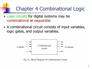
Decoder • A decoder is a circuit that creates an output based on the binary states of a given input • Do the opposite of encoder
Decoder Example: 3 to 8 Binary Decoder
/Bl D C B A a b c d e f g 0 x x x x 0 0 0 0 0 0 0 1 0 0 0 0 1 1 1 1 1 1 0 1 0 0 0 1 0 1 1 0 0 0 0 1 0 0 1 0 1 1 0 1 1 0 1 1 0 0 1 1 1 1 1 1 0 0 1 1 0 1 0 0 0 1 1 0 0 1 1 1 0 1 0 1 1 0 1 1 0 1 1 1 0 1 1 0 0 0 1 1 1 1 1 1 0 1 1 1 1 1 1 0 0 0 0 1 1 0 0 0 1 1 1 1 1 1 1 1 1 0 0 1 1 1 1 0 0 1 1 1 1 0 1 0 0 0 0 1 1 0 1 1 1 0 1 1 0 0 1 1 0 0 1 1 1 1 0 0 0 1 0 0 0 1 1 1 1 1 0 1 1 0 0 1 0 1 1 1 1 1 1 0 0 0 0 1 1 1 1 1 1 1 1 1 0 0 0 0 0 0 0 -- don’t care inputs -- Decoder Example:Seven Segment Decoder • A seven segment decoder has 4-bit BCD input and the seven segment display code as its output • In minimizing the circuits for the segment outputs all non-decimal input combinations (1010, 1011, 1100,1101, 1110, 1111) are taken as don’t-cares
Decoder • Application Example:
Code Converters • Device that converts one type of binary representation to another • Example: BCD to binary and binary to Gray code. • To convert binary to Gray code or Gray code to binary, we use X-OR gates. How???