Download
1 / 74
790 likes | 1.59k Views
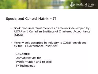
Control IT Hardware (AC800 M/C) & SoftController. A suite of IEC 61131-3 compatible controllers. AC 800M – the new Modular Controller designated for binary control as well as advanced control applications AC 800C – the Compact Controller for small, yet advanced applications

E N D
A suite of IEC 61131-3 compatible controllers • AC 800M – the new Modular Controller designated for binary control as well as advanced control applications • AC 800C – the Compact Controller for small, yet advanced applications • SoftControl – the controller that runs on a PC providing high performance at low cost
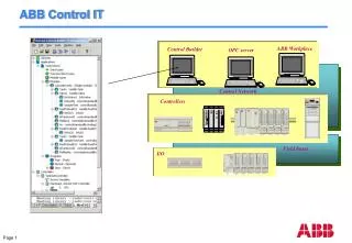
ControlIT AC 800M Hardware • AC 800M • Modular and flexible concept, DIN-rail mounted • Built in redundant Ethernet • Very low power consumption • Hot swap of communication- and I/O modules • Local and remote I/O options • Industry quality hardware with excellent EMC and MTBF properties
AC 800M Controller with a S800 I/O Module AC 800M I/O System Communication Interface Processor Module S800 I/O Module
Hardware mapped to Control Builder 1 2 3 4 5 6 7 8 1 6 5 4 3 2 7 8
Processor Module PM860 - Processor TP830 - Baseplate Communication Interfaces CI851 – Profibus CI852 – Foundation Fieldbus CI853 – RS232-C Power Supply SD821 - 24 V d.c. regulated @ 2.5 A SD822 - 24 V d.c. regulated @ 5 A SD823 - 24 V d.c. regulated @ 10 A Battery Backup SB821- External Backup Base components for AC 800M
MPC860/48MHZ Motorola Power PC 8 MB RAM 5 MB for application program 3 MB for executable firmware Mounted on the module 2 MB System FLASH PROM For non-volatile storage of firmware and license key Mounted on the module Optical Modulebus to connect clusters of S800 I/O modules A connector for Compact Flash (not included in this release) Two Ethernet ports for connection to the control network CN1, CN2 Two serial ports (COM3, COM4) COM3 is an RS232-C port with modem control signals COM4 is isolated and used for the connection of the configuration tool Electrical Modulebus is used for connection clusters of S800 I/O directly to the baseplate CEX-bus is used for extending the on-board communication ports with communication interface modules Processor Module
Switch-mode power converters Converting a.c. Mains supply voltage to a regulated 24 V d.c. Input can be either 115 V a.c. or 230 V a.c Redundant or non redundant When a redundant power supply is connected to a common load, you need a voting device, SS822, to combine two outputs into one via diodes The CPU module does has no requirement for a UPS It has a 5 ms reservoir to safely shutdown The power supply handles short power interruptions (<20 ms) Available modules SD 823 24 V d.c. regulated @ 10 A SD 822 24 V d.c. regulated @ 5 A SD 821 24 V d.c. regulated @ 2.5 A Power Supply
Internal battery Up to one month (720 hours) Lithium Battery 3.6 V, 950 mAh. External battery module - SB821 Lithium battery, 3.6 V 16 Ah A minimum of 18 months Mounted on the DIN rail and connected to the CPU via cable Battery Backup External battery Internal battery External battery Connection
Local I/O – S800 12 local I/O modules per cluster 24 with optical modem 7 clusters x 12 I/O modules of local on the Modulebus Up to 96 local I/O Modules Remote I/O via Profibus Foundation Fieldbus and Advant Fieldbus to come Recommened to use ABB I/O S900, S800 and S200 Field Communication Interface (FCI) is used to connect the I/O modules to the PROFIBUS There is no physical limit for the number of I/Os that can be connected to AC 800M Recommendation ~600-700 I/O per controller The memory for the application sets the limit The hardware is relatively cheap Buy an extra controller I/O System
Local I/O Up to 96 modules Remote I/O via Profibus I/O System CI851 Profibus PM860 CPU PM860 CPU 12 I/O Modules Optical CI830 FCI 12 I/O modules TB820 OpticalModem 12 I/O modules Up to 24 modules per stations CI830 FCI Optical 12 I/O modules TB820 OpticalModem 12 I/O modules TB820 OpticalModem 12 I/O modules Up to 7 clusters and 200m between clusters Up to 5 PROFIBUS segments Up to 32 stations per segment Up to 24 modules per stations Up to 384 DI/DO and 192AI/AO per station
AC 800M / S800 I/O Interconnection TB805 AO810 AO810 AI810 AO810 AO810 PM810 AI810 CI851 TK801V003/6/12 TB850V007 See note 1 TB851 TB806 See note 3 AO810 AO810 AI810 AO810 AO810 AI810 CI851 See note 2 DO810 DI810 DO810 TB820 DI810 TK811V015/050/150 See note 5 To addition module clusters DO810 DI810 DO810 CI830 DI810 TB810 See note 4 DI810 TB820 DI810 DO810 DO810
Modulebus Extension & Termination TB805 TB806 DIN-Rail TK801V003/006/012 Note 3
I/O Module on Compact & Extended MTUs I/O Modules Extended MTU Typical Compact MTU with I/O Module CI830 Compact MTU Typical Extended MTU with I/O Module
AC 800M Connectors for Optical Modulebus Duplex Fiber Optic Cable Connector TK811V015/050/150 Rx Tx TK812V015/050/150 Simplex Fiber Optic Cable Connector Front View Note 1 For connection from PM810 to TB820
TB820 Optical Modulebus Connection TB820 Optical ModuleBus Interface Connectors (X4, X5) TK811V015/050/150 Rx X4 Tx Duplex Fiber Optic Cable Connector Rx TK812V015/050/150 X5 Tx Simplex Fiber Optic Cable Connector Front View Note 5
CEX Extension & Termination Note 2
CEX Extension & Termination Note 2
Supported S800 I/O Modules (Local & Remote) S800 I/O Modules S800 I/O I.S. Modules S800L I/O Modules
Supported S200 I/O Modules (Remote I/O) Via 200-APB12 PROFIBUS Adapter S200L I/O Modules S200 I/O Modules S200L I/O Modules
CI851 – Profibus Interface Power from the processor module TP851 – Baseplate Profibus DP must be terminated on both sides It is possible to connect any standard PROFIBUS I/O via CI851 For example S800 I/O or S200 I/O PROFIBUS Support
PROFIBUS Connection - CI830 & TB820 Connector for TB810 TB820 Modulebus Optical Port Power Supply Connections Profibus-DP Connector Note 4 CI830
AC 800M, Profibus integration S800 I/O Profibus-PA via standard segmentcoupler Profibus-DP S900 I/O Profibus-PA DP/PA Converter
CI852 – Foundation Fieldbus H1 Interface Power from the processor module TP852 – Baseplate Up to 32 Foundation Fieldbus Devices Foundation Fieldbus (In future release)
AC 800M ,FF integration Communication with FF-instruments is easily performed via IEC 61131-3 function blocks FF H1
CI853 – RS232-C Two serial ports Power from the processor module TP853 – Baseplate A RS232-C channel, with full modem support, can be connect to COM1 or COM2 For cables longer than 15m a short distances modem, TC562, must be used Up to 12 km, depending on the transmission speed Available Protocols Please see screen dump to the right Serial Interface – RS232-C
CEX Bus in the communication bus TB 850 CEX-bus termination shall always be installed on the last unit CEX extension cable TK850 (0.7m) to mount the modules on another DIN-rail CEX Extension and Termination
The Modulebus connects the local I/O A terminator, TB807, must always be mounted on the last I/O module on the Modulebus Will support direct connection to Drives in the future Modulebus Extension and Termination
Mounted on a horizontal DIN rail Locking device to connect to the DIN rail to get grounding The locking device can be in OPEN, SLIDE or LOCKED AC800M & S800I/O has protection class IP20 To get higher protection we recommend the following cabinets with protection class IP54 RM550 – Floor mounted RE820 – Wall mounted Installation Example of Wall mounted
Processor Module – PM210 18,432 MHz 2 Mb RAM and 2 Mb Flash PROM On board I/O Modules 10 DI, 6 DO Two on-board RJ-45 jacks for RS-232 channels COM 0 – The port for the Control Builder COM 1- full set of modem control signals Two slots for optional communication plug-in boards are provided Serial Links Ethernet PROFIBUS-DP master of class 1 FOUNDATION Fieldbus link master (future) Battery back-up module - SB210 1 slot for an optional battery plug-in board with a real-time clock and a lithium battery AC 800C Main Module
Hardware mapped to Control Builder 8 7 1 1 2 3 4 5 6 7 8 6 5 2 4 3
Horizontally and vertically mounted on the DIN rail The AC 800C, S200, S200L and S800 I/O-unit have all protection class IP 20 Installation
AC 800C / S200/S200L/ S800 I/O Modules Interconnection Programming Terminal Central I/O Remote I/O AC 800C S800 I/O S200/S200L I/O Profibus-DP S200/S200L I/O
On-board I/O 10 DI and 6 DO on board 24 V DC The inputs and outputs are filtered and galvanically isolated by optocouplers Local Input/Output (I/O) units 8 S200 Local I/O Modules two rows by means of the extension cables CE1 or CE3. 8 Extra via a TK210 cable and a 200 AIO adapter Remote I/O Modules PROFIBUS-DP can be used for connection of remote I/O units, for instance S200/S200L and S800 I/O units The total number of I/O units connected (central and remote) to the controller are 32 I/O units How to connect I/O Modules
On-board I/O 10 DI and 6 DO on board 24 V DC The inputs and outputs are filtered and galvanically isolated by optocouplers A separate two-pole plug-in screw connector for the external +24 V DC power supply The unit is not damaged if the polarity is reversed On board I/O
Local Input/Output (I/O) units 8 S200 Local I/O Modules two rows by means of the extension cables CE1 or CE3 0.3 and 0.9 m respectively 8 Extra via a TK210 cable and a 200 AIO adapter (length 0.5, 1.0, or 2.5 m) Note that a TK210 cable longer than 0.9 m is not allowed in hazardous locations according to UL1604 Local I/O
Supported S200 I/O (Local & Remote) S200C I/O Modules S200 I/O Modules S200L I/O Modules
To Control Builder Via a serial port using the PPP protocol, or alternatively via Ethernet Serial Interfaces Available protocols are Siemens 3964R (as master), COMLI, MODBUS RTU (as master) and MMS. User-defined protocols may also be used Fieldbus Support PROFIBUS FOUNDATION Fieldbus On-board serial Communication COM 0 can receive and transmit signals COM 0 is the default channel for the programming station tool port COM 1 has a full set of modem control signals Each channel has LEDs indicating the status of transmit and receive activities RS-232 is a point-to-point communication standard with a maximum cable length of 15 meters AC 800C Communication Possibilities
Communication Extensions Ethernet Communication Board CI272 Profibus Communication Board CI274 RS-232 Communication Board CI271
RS-232 Communication Board CI271 (Option) There are two RJ-45 jacks for RS-232 channels Full set of modem control signals This gives a multiple RS-232 point-to-point communication with e.g. printers, scales, bar codes, controllers, and for multiple protocols (COMLI, Modbus, etc) Communication Extensions - Serial
Ethernet Communication Board CI272 (Option) Enables a network consisting of many interconnected controllers, operator stations and servers Communication via MMS It has one RJ-45 jack for Ethernet 10BASE-T (twisted pair, max. cable length 100 m) Communication Extensions - Ethernet