Download
1 / 66
920 likes | 1.34k Views
Von Neumann Architecture. Goals. Understand how the von Neumann architecture is constructed. Understand how the von Neumann architecture works. Understand how to program in basic a assembly language. Where Are We?.

E N D
Goals • Understand how the von Neumann architecture is constructed. • Understand how the von Neumann architecture works. • Understand how to program in basic a assembly language.
Where Are We? • We have spent several weeks now, building our understanding of computer organization. • We started with transistors, moved up a level to gates, and then up a level to circuits. • Our next step is a key one: we will combine circuits together to build functional units of computer operation.
Ladder of Abstraction • It is worth reminding ourselves how we got here: • Climbing up the ladder of abstraction, the process is to take the functional units of one level, combine them, and move this combined unit to the next unit of abstraction • As we move to this new level, the level of sub-components, we need to remember that this level is built from the components of previous levels
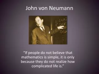
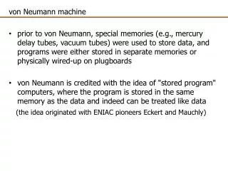
Sub-Components • At the onset, computers required hardware changes to work on new problems; some historians say that this early stage of “programming” was wiring. • Clearly, requiring hardware changes with each new programming operation was time-consuming, error-prone, and costly • If you recall from the movie The Machine That Changed the World, one of the key contributors to computer evolution was John von Neumann
The Stored Program Concept • Von Neumann’s proposal was to store the program instructions right along with the data • This may sound trivial, but it represented a profound paradigm shift • The stored program concept was proposed about fifty years ago; to this day, it is the fundamental architecture that fuels computers. • Think about how amazing that is, given the short shelf life of computer products and technologies…
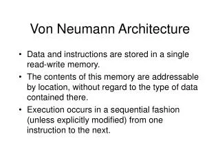
The Stored Program Concept and its Implications • The Stored Program concept had several technical ramifications: • Four key sub-components operate together to make the stored program concept work • The process that moves information through the sub-components is called the “fetch execute” cycle • Unless otherwise indicated, program instructions are executed in sequential order
Four Sub-Components • There are four sub-components in von Neumann architecture: • Memory • Input/Output (called “IO”) • Arithmetic-Logic Unit • Control Unit • While only 4 sub-components are called out, there is a 5th, key player in this operation: a bus, or wire, that connects the components together and over which data flows from one sub-component to another • Let’s look at each sub-component in more detail …
Memory • As you already know, there are several different flavors of memory • Why isn’t just one kind used? • Each type of memory represents cost/benefit tradeoffs between capability and cost …
Memory Types: RAM • RAM is typically volatile memory (meaning it doesn’t retain voltage settings once power is removed) • RAM is an array of cells, each with a unique address • A cell is the minimum unit of access. Originally, this was 8 bits taken together as a byte. In today’s computer, word-sized cells (16 bits, grouped in 4) are more typical. • RAM gets its name from its access performance. In RAM memory, theoretically, it would take the same amount of time to access any memory cell, regardless of its location with the memory bank (“random” access).
Memory Types: ROM • It gets its name from its cell-protection feature. This type of memory cell can be read from, but not written to. • Unlike RAM, ROM is non-volatile; it retains its settings after power is removed. • ROM is more expensive than RAM, and to protect this investment, you only store critical information in ROM …
Memory Types: Registers • There is a third, key type of memory in every computer – registers. • Register cells are powerful, costly, and physically located close to the heart of computing. • We will see later that among the registers, several of them are the main participants in the fetch execute cycle.
Memory Types: Other • Modern computers include other forms of memory, such as cache memory. • Remember, memory types exist at different trade offs. • The study of memory organizations and access schemes is an innovative one within Computer Science. In your life time, you should expect to see numerous innovations in memory types and capabilities.
What’s Up with Memory • Regardless of the type of memory, several concepts apply in this key component. • Cell size or cell width: a key concept within memory is how many individual memory cells (which we now know are switches!) are addressed at a time. • At a minimum, this is a byte (8 bits) in today’s computers, but to support all data types and operations, cell size can be larger (a word, for instance, at 16 bits).
What’s Up with Memory • Cell address and contents: another key concept is to recognize that all cells have an address, and can contain data contents. • The cell address is a label (like a zip code) that identifies a particular cell. • The cell contents are whatever data is stored at a given address location.
What’s Up with Memory • Two other key concepts in the study of memory are memory size and address space. • Memory size refers to the number of addressable cells – how many different memory locations a computer has. • Address space refers to the range of addressable cell labels. Cell labels begin with the number 0. So, if you had a computer with 2n memory size, its address space would be 2n -1.
What’s Up with Memory • Don’t forget that the memory labels are themselves binary numbers! • One of the special registers we talked about earlier is a register whose job it is to hold address locations. • Engineers need to know how big to make this register, so that it could hold the address of any given memory location, even the one with the biggest address.
What’s Up with Memory • The special register is called the MAR – the machine address register. • For a machine with 2n address cells, the MAR must be able to hold a number 2n - 1 big.
Memory Operations • Two basic operations occur within this subcomponent: a fetch operation, and a store. • The fetch operation: • A cell address is loaded into the MAR. • The address is decoded, which means that thru circuitry, a specific cell is located. • The data contents contained within that cell is copied into another special register, called a Machine Data Register (MDR). • Note that this operation is non-destructive – that is, the data contents are copied, but not destroyed.
Memory Operations • The second memory operation is called a store. • The fetch is like a read operation; the store is like a write operation • In the store, the address of the cell into which data is going to be stored is moved to the MAR and decoded. • Contents from yet another special register, called an accumulator, are copied into the cell location (held in the MAR). • This operation is destructive, meaning that whatever data was originally contained at that memory location is overwritten by the value copied from the accumulator.
I/O: Input and Output • There is both a human-machine interface and a machine-machine interface to I/O. • Examples of the human-machine interface include a keyboard, screen or printer. • Examples of the machine-machine interface include things like mass storage and secondary storage devices. • Input and output devices are the least standardized of the various sub-components, which means that you have to pay extra special attention to make certain that your input or output devices are compatible with your machine.
The ALU • The third component in the von Neumann architecture is called the Arithmetic Logic Unit. • This is the subcomponent that performs the arithmetic and logic operations for which we have been building parts. • The ALU is the “brain” of the computer.
The ALU • It houses the special memory locations, called registers, of which we have already considered. • The ALU is important enough that we will come back to it later, For now, just realize that it contains the circuitry to perform addition, subtraction,multiplication and division, as well as logical comparisons (less than, equal to and greater than).
Control Unit • The last of the four subcomponents is the Control Unit. • The control unit is the work horse that drives the fetch and execute cycle. • Remember we said that in memory, a cell address is loaded into the MAR – it is the control unit that figures out which address is loaded, and what operation is to be performed with the data moved to the MDR. • We will come back and look in detail at how the Control Unit performs this task.
Stored Program Concept • We saw that it was von Neumann’s organizational scheme that was adopted in computer architecture. • This architecture was largely driven by the decision to store program code along with data. • Once this decision was made, several by-product engineering requirements emerged.
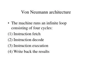
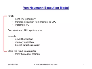
Engineering Needs • We indicated that for cost/benefit reasons, data and program instructions are translated into binary form and stored in RAM. • As the information is needed, it is moved to the high speed, costlier registers where it is processed. • This process occurs in a cycle: fetch information to the registers, and execute it there, fetch the next information from the registers, and execute it, etc. • The cycle is referred to as the “fetch execute” cycle.
Engineering Needs • Once we know on which data we should be working, we know how to build circuitry to perform processing operations. (We can add, subtract, divide and compare). • One of the things we glossed over in our first discussion, however, is how we figure out what data to be working on, and exactly which operation to perform • Specifically, this is what we need to be able to do: • Build a circuit that will allow us to take whatever number is in the MAR, and use this number to access a specific memory cell. • Build a circuit that will allow us to choose which data results should be placed in the MDR. • This magic happens in the Control Unit
Choosing a Memory Location • Let’s tackle the initial requirement first: how do we determine which address location holds the data on which we need to operate. • Remember we said that there is a special register, called the MAR that holds an address -- a binary number. • We need some circuitry to read that number, and based on its value, find exactly the correct address location to read. • The circuit is called a decoder …
Decoder Circuits • The MAR is connected to a decoder circuit. • This circuitry will identify the correct memory cell. • Let’s figure out how this works …
Decoder Circuits • Initially, think about the decoder circuit as a black box. • Going into the black box are N input lines, (which emerge from the MAR). • Going out of the black box are 2n output lines (with each output line connecting to a specific memory cell in RAM).
Decoder Circuit: An Example • Let’s start small: imagine a computer with 4 memory cells in RAM, where our formula now is: 2n, thus n = 2 so that 2n=4. • The MAR will need to be N cells big, and the biggest number it would have to hold is the address range, 2n-1=3. • Let’s build the decoder circuit …
First, the Problem Statement • Design a circuit with 2 input lines (a, b) and 4 output lines (d0,d1,d2,d3) • The output lines are uniquely high if and only if the following conditions are met: • d0 is high IFF both inputs are low • d1 is high IFF a is low and b is high • d2 is high IFF a is high and b is low • d3 is high IFF both a and b are high
Next, the Boolean Sub-Expressions • For those places in our output chart with high values (1’s), we have the following a,b input conditions: • d0 = ~a * ~b • d1 = ~a * b • d2 = a * ~b • d3 = a * b
Circuit Diagram – Decoder Circuit To the MDR d0 d1 d2 d3 a b MAR
Decoder Circuit Example • Assume the contents of the MAR are 01. • Which line would fire? • Remember the Boolean expression:(~a • b) • This would cause the d1 line to fire, which in turn is connected to the d1 memory location. • The d1 memory location is read non-destructively, and a copy of its contents (let’s assume the contents equal 61), is copied to the MDR.
d0 d1 61 d2 d3 a b MAR Circuit Diagram – Decoder Circuit
Scaling Issue • We have built a viable decoder circuit, and illustrated how this control circuit could perform in translating between the address label contained in the MAR and obtaining contents of the referenced location. • At some point, however, the model isn’t scaleable – too much space required for a linear layout. • Computers utilize a 2-dimensional approach in decoder operation, using a row/column MAR addressing scheme to identify specific address locations. • A 2-D grid is illustrated on the next slide …
One Problem Solved • Well, we have figured out how to use circuitry to decode the contents of the MAR to identify a specific memory location. • We still need to figure out how to interpret the results of the ALU circuitry to load a correct process answer into the MDR.
Multiplexor Circuits • Remember, we said that the ALU actually performs all operational processing on 2 given inputs. • Thus, if the inputs are 4 and 2, calculations for 4 + 2, 4 * 2, 4-2, 4 >= 2, etc. are all performed in parallel. • What we need to be able to do is to select the correct answer from among all those calculated.
Multiplexor Circuits • A multiplexor is a circuit with 2n input lines and 1 output line. • The function is serves is to select exactly one of its input lines and copy the binary value on that input line to its single output line.
Multiplexor Magic • The multiplexor chooses the correct input line to pass thru to the output line by using a second set of N lines called selector lines. • So, the total number of input lines in a multiplexor are 2n + N. • The first set of input lines are numbered from 0 to 2n-1, while the selector lines are numbered from 0 to N, such that there is exactly one selector line for each input line. • Each selector line can be set to either a 1 or a 0. • Thus, the binary number that appears on the selector lines can be interpreted as the identification number of the input line to be passed thru.
Where We’ve Been • We have been touring the von Neumann architecture of 4 sub-components. • We have figured out how to build the appropriate circuitry to perform arithmetic and logic operations on the data contained at specific memory locations. • What we don’t know how to do is to figure out which arithmetic or logic operations need to be performed and in what order.
The Control Unit • The mastermind behind these final pieces of our operational model is the Control Unit • It is the Control Unit that fuels the stored program concept • To do its job, the Control Unit has several tools • Special memory registers • “Wired” understanding of an Instruction Set
Toolset • Let’s look at the toolset first, and then how it is deployed • Special Memory Registers • The Control Unit must keep track of where it is within a program, and what it should do next • Two special registers are used to accomplish this: • A program counter, typically referred to as a PC, holds the address of the NEXT instruction to be executed • An instruction register, typically referred to as an IR, holds an instruction fetched from memory
Toolset (Two) • Along with the special registers, the Control Unit utilizes special circuitry, called an instruction decoder • The instruction decoder is a typical decoder circuit, and its purpose is to read an instruction from the IR, and activate the appropriate circuit line