Download
1 / 25
300 likes | 640 Views
Digital Arithmetic. Wen-Hung Liao, Ph.D. Objectives. Perform binary addition, subtraction, multiplication, and division on two binary numbers. Add and subtract hexadecimal numbers. Know the difference between binary addition and OR addition.

E N D
Digital Arithmetic Wen-Hung Liao, Ph.D.
Objectives • Perform binary addition, subtraction, multiplication, and division on two binary numbers. • Add and subtract hexadecimal numbers. • Know the difference between binary addition and OR addition. • Compare the advantages and disadvantages among three different systems of representing signed binary numbers. • Manipulate signed binary numbers using the 2's complement system. • Understand the BCD adder circuit and the BCD addition process. • Describe the basic operation of an arithmetic/logic unit.
Objectives (cont’d) • Employ full adders in the design of parallel binary adders. • Cite the advantages of parallel adders with the look-ahead carry feature. • Explain the operation of a parallel adder/subtractor circuit. • Use an ALU integrated circuit to perform various logic and arithmetic operations on input data. • Read and understand the IEEE/ANSI symbol for a parallel adder. • Analyze troubleshooting case studies of adder/subtractor circuits. • Program a PLD to operate as a 4-bit full adder.
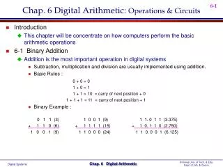
Binary Addition • Performed in the same manner as the addition of decimal numbers. • Most important arithmetic operation in digital systems, since subtraction, multiplication and division are all based on addition.
Representing Signed Numbers • Sign-magnitude system: left most bit as sign bit (0 for +, 1 for -), remaining bits as the magnitude. • Problems: • How to perform addition? • Two zeros: 1 0000 and 0 0000
1’s and 2’s-Complement Form • 1‘s complement: change 0 to 1 and 1 to 0. • 2’s complement: take 1’s complement and add 1 to the LSB. • Examples: +13, -9,+3,-2,-8 • Negation vs. complement
2’s Complement • Range of values can be represented using 1 sign bit and N magnitude bits:-2^N to 2^N-1 • 1000 = -2^3 =-8 • 10000 = -2^4 = -16…
Addition in 2’s Complement Form • Case I: Two positive numbers • Case II: Positive number and smaller negative number • Case III: Positive number and larger negative number • Case IV: Two negative numbers • Case V: Equal and opposite numbers
Subtraction in 2’s Complement • A – B = A + (-B) • Arithmetic overflow: results of addition or subtraction fall outside the range of values that can be represented.
Binary Multiplication • Similar to multiplication of decimal numbers • 1001 x 1011 • What about the sign? • Overflow?
Binary Division • 1001 divided by 11
BCD Addition • Sum equals 9 or less: digit-by-digit addition • Sum greater than 9: • Example: 6 + 7 • Add 6 (0110) to correct the result (will produce a carry)
Hexadecimal Arithmetic • Hex addition • Hex subtraction • Convert to binary,take 2’s complement, convert back to Hex • Subtract each hex digit from F, then add 1 • Hex representation of signed numbers: • 3A +58 • E5 -29 • When MSD >=8, negative
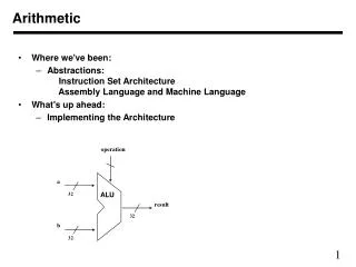
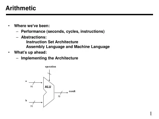
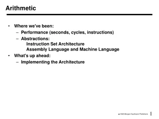
Arithmetic Circuits • Parallel Binary Adder (Figure 6-5*): sum and carry bit.
Design of a Full Adder • Figure 6-6 (Truth Table) • Figure 6-7* • Half adder: take 2 inputs and generate sum and carry bits.
Four-Bit Parallel Adder • Complete parallel adder with registers (Figure 6-9):
Register Notation • Register notation: [A]: the content of register A • Example: [A]=1011 means that A3=1, A2=0, A1=1, A0=1.
Carry Propagation • For parallel adders, sum bit generated in the last position (MSB) depended on the carry that was generated by the addition in the first position (LSB). • More delay for addition of 32 or 64 bit numbers. • Use look-ahead carry to reduce propagation delay.
Integrated-Circuit Parallel Adder • 4-bit parallel adder: 74HC283 • Cascading parallel adders
2’s Complement System • Figure 6.11: addition (C0=0) • Figure 6.12: subtraction (C0=1)
Combined Addition and Subtraction • Figure 6-13
BCD Adder • How to detect when sum > 9? • X=S4+S3(S2+S1) • Figure 6-14
ALU ICs • 74LS382/74HC382 • CLEAR, B minus A, A minus B, A plus B, A XOR B, A+B, AB, preset • Expanding the ALU: combining 2 4-bit ALUs. • IEEE symbols