Download
1 / 10
100 likes | 102 Views
Learn about the equilibrium of a particle and a rigid body. Understand the concepts of forces, moments, support reactions, and solving equilibrium problems.

E N D
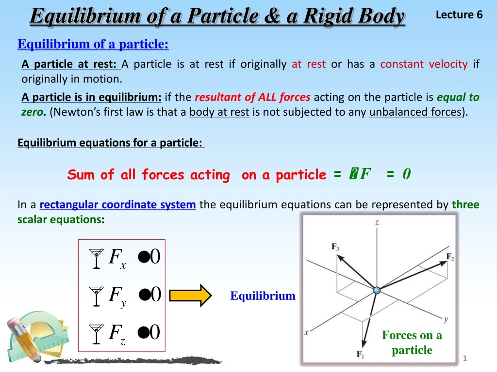
Equilibrium of a Particle & a Rigid Body Lecture 6 Equilibrium of a particle: A particle at rest: A particle is at rest if originally at rest or has a constant velocity if originally in motion. A particle is in equilibrium: if the resultant of ALL forces acting on the particle is equal to zero. (Newton’s first law is that a body at rest is not subjected to any unbalanced forces). Equilibrium equations for a particle: Sum of all forces acting on a particle = F = 0 In a rectangular coordinate systemthe equilibrium equations can be represented by three scalar equations: Equilibrium Forces on a particle
Equilibrium of a Particle & a Rigid Body Lecture 6 Equilibrium of a Rigid Body: • In contrast to the forces on a particle, the forces on a rigid-body are not usually concurrent and may cause rotation of the body (due to the moments created by the forces). y • For a rigid body to be in equilibrium, the net force as well as the net moment about any arbitrary point ( O) must be equal to zero. x 2 D Equilibrium in 2D: F = 0 F = 0 (no translation) (no translation) Equilibrium in 3D: MO= 0 MO= 0 (no rotation) (no rotation) And: MX= 0, MY= 0,MZ= 0 3 D
THE PROCESS OF SOLVING RIGID BODY EQUILIBRIUM PROBLEMS Lecture 6 For analyzing any actual system for equilibrium, the best way is to follow the procedure for the example mentioned below: Given: An operator applies (20 lb) to the foot pedal. A spring with (k = 20 lb/in) is stretched (1.5 in ). For analyzing an actual physical system, first we need to create an idealized model(above right). Draw a free-body diagram (FBD) showing all the external (active and reactive) forces. Show all the external forces and couple moments. These typically include: a) applied loads, b) support reactions, and, c) the weight of the body. Idealized model Label loads and dimensions on the FBD: All known forces and couple moments should be labeled with their magnitudes and directions. Finally, apply the equations of equilibrium to solve for any unknowns. FBD
EXAMPLES of (2 D) Equilibrium: Lecture 6 Example 1: A beam (AB) is supported by pins (A & C), a vertical force (4 kN) is applied at point (B). Find the support reactions at (A and C). 4 kN 4 kN AY AY 1.5 m 1.5 m 1.5 m 1.5 m Solution procedures: AX AX 1. Put the x and y axes respectively. 2. Determine if there are any two-force members. 3. Draw a complete FBD of the boom. B C A A B C 45° FC Note: Upon recognizing CD as a two-force member, the number of unknowns at C are reduced from two to one. Now, using E - of - E, we get, FBD of the beam: y y + MA = FC sin 45 1.5 – 4 3 = 0 Fc = 11.31 kN or 11.3 kN x x • + FX = AX + 11.31 cos 45 = 0; • AX = – 8.00 kN • + FY = AY + 11.3 sin 45 – 4 = 0; • + A Y = – 4.00 kN FC cos 45o Note:that the negative signs means that the reactions have the opposite direction to that shown on FBD. FC sin 45o
EXAMPLES of (2 D) Equilibrium: Lecture 6 Example 2: Two smooth pipes, each having a mass of 300 kg, are supported by the tines of the tractor fork attachment. Determine all the reactive forces ? Solution procedures: Isolate the object from its surroundings, Draw the outline of the object; consider all dimensions and angles, Include all forces and couple moments, Label known forces and moments with their proper magnitudes and directions, Unknown forces and moments should be represented with letters. Idealized model For Pipe A: • The moment equations can be determined about any point. Choosing the point where the maximum number of unknown forces are present simplifies the solution. D y C x 2943 sin30o O 2943 cos30o
Continue Example 2: Lecture 6 Or: y x 2943 sin30o For Pipe B: D 2943 cos30o x y 0.7 m For both Pipes ( A & B ): • When pipes A and B are considered as one object, you neglect the reaction forces between them. C O
Lecture 6 Example 3: The lever ABC in pin supported at A and connected to a short link BD as shown in figure. If the weight of the members is negligible, determine the force of the pin on the lever at A? Solution • As shown in figure, the short link BD is a two force member, so the resultant forces at pins D and B must be equal, opposite and collinear. Although the magnitude of the force is unknown, the line of action is known since it passes through B and D. • Lever ABC is a three force member, and therefore, in order to satisfy moment equilibrium, the three nonparallel forces acting on it must be concurrent at Point ( O ) as shown in below figure. • Note, that the force F on the lever at ( B ) is equal but opposite to the force ( F ) acting at ( B ) on the link ( BD ). • the distance ( CO ) must be equal to ( 0.5 M ), since the lines of action of ( F ) and the ( 400 N ) force are known.
Continue Example 3: Lecture 6
Lecture 6 Example 4:The homogenous plate shown in figure has a mass of (100 kg) and is subjected to a force and couple along its edges, if it is supported in the horizontal plane by a roller at (A), a ball and socket joint at (B), and a cord at (C), determine the components of reaction at these supports? Solution • FBD. There are fiveunknown reactions acting on the plate, as shown in figure. Each of these reactions is assumed to act in a positive coordinate direction. Fz = 0; Az + Bz + Tz – 300 N – 981 N = 0 Fz = 0; Az + Bz + Tz – 1281 N = 0 …. ( 1 )
Continue Example 4: Lecture 6 • Forces that are parallel to an axis or pass through it, create no moment about that axes. Hence, summing moments about the positive ( x and y axes), we have: