Download
1 / 28

E N D
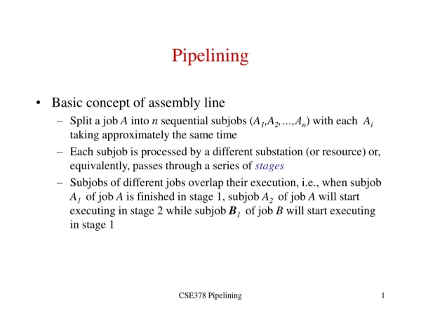
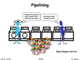
Pipelining The speed of execution of programs is influenced by many factors. One way to improveperformance is to use faster circuit technology to implement the processor and the mainmemory. Another possibility is to arrange the hardware so that more than one operationcan be performed at the same time. In this way, the number of operations performed persecond is increased, even though the time needed to perform any one operation is notchanged. Pipelining is a particularly effective way of organizing concurrent activity in a computersystem. The basic idea is very simple. CENG 222 - Spring 2012-2013 Dr. Yuriy ALYEKSYEYENKOV
Pipelining It is frequently encountered in manufacturingplants, where pipelining is commonly known as an assembly-line operation. Readers areundoubtedly familiar with the assembly line used in automobile manufacturing. The firststation in an assembly line may prepare the automobile chassis, the next station adds thebody, the next one installs the engine, and so on. While one group of workers is installingthe engine on one automobile, another group is fitting a body on the chassis of a secondautomobile, and yet another group is preparing a new chassis for a third automobile. Althoughit may take hours or days to complete one automobile, the assembly-line operationmakes it possible to have a new automobile rolling off the end of the assembly line everyfew minutes. CENG 222 - Spring 2012-2013 Dr. Yuriy ALYEKSYEYENKOV
Pipelining Consider how the idea of pipelining can be used in a computer. The five-stage processororganization ıntroduced before allow instructionsto be fetched and executed one at a time. It takes five clock cycles to complete the executionof each instruction. Rather than wait until each instruction is completed, instructions canbe fetched and executed in a pipelined manner, as shown in figure. The five stagescorresponding to those are labeled as Fetch, Decode, Compute, Memory, andWrite. Instruction Ijis fetched in the first cycle and moves through the remaining stagesin the following cycles. In the second cycle, instruction Ij+1 is fetched while instructionIjis in the Decode stage where its operands are also read from the register file. CENG 222 - Spring 2012-2013 Dr. Yuriy ALYEKSYEYENKOV
Pipelining In thethird cycle, instruction Ij+2 is fetched while instruction Ij+1is in the Decode stage andinstruction Ij is in the Compute stage where an arithmetic or logic operation is performedon its operands. Ideally, this overlapping pattern of execution would be possible for allinstructions. Although any one instruction takes five cycles to complete its execution,instructions are completed at the rate of one per cycle. CENG 222 - Spring 2012-2013 Dr. Yuriy ALYEKSYEYENKOV
Pipelining Figure indicates how the five-stage organization can be pipelined.In the first stage of the pipeline, the program counter (PC) is used to fetch a new instruction.As other instructions are fetched, execution proceeds through successive stages. At anygiven time, each stage of the pipeline is processing a different instruction. Informationsuch as register addresses, immediate data, and the operations to be performed must becarried through the pipeline as each instruction proceeds from one stage to the next. Thisinformation is held in interstage buffers. These include registers RA, RB, RM, RY, and RZ, the IR and PC-Temp, and additional storage. CENG 222 - Spring 2012-2013 Dr. Yuriy ALYEKSYEYENKOV
Pipelining • Interstage buffer B1 feeds the Decode stage with a newly-fetched instruction. • Interstage buffer B2 feeds the Compute stage with the two operands read from the registerfile, the source/destination register identifiers, the immediate value derived fromthe instruction, the incremented PC value used as the return address for a subroutinecall, and the settings of control signals determined by the instruction decoder. Thesettings for control signals move through the pipeline to determine theALUoperation,the memory operation, and a possible write into the register file. • Interstage buffer B3 holds the result of the ALU operation, which may be data to bewritten into the register file or an address that feeds the Memory stage. In the case ofa write access to memory, buffer B3 holds the data to be written. These data were readfrom the register file in the Decode stage. The buffer also holds the incremented PCvalue passed from the previous stage, in case it is needed as the return address for asubroutine-call instruction. • Interstage buffer B4 feeds the Write stage with a value to be written into the registerfile. This value may be the ALU result from the Compute stage, the result of theMemoryaccess stage, or the incremented PC value that is used as the return addressfor a subroutine-call instruction. CENG 222 - Spring 2012-2013 Dr. Yuriy ALYEKSYEYENKOV
Pipelining Issues There was depictedthe ideal overlap of three successive instructions. But, there are timeswhen it is not possible to have a new instruction enter the pipeline in every cycle. Considerthe case of two instructions, Ijand Ij+1, where the destination register for instruction Ijis a source register for instruction Ij+1. The result of instruction Ij is not written into theregister file until cycle 5, but it is needed earlier in cycle 3 when the source operand is readfor instruction Ij+1. If execution proceeds as shown in figure, the result of instructionIj+1would be incorrect because the arithmetic operation would be performed using the oldvalue of the register in question. To obtain the correct result, it is necessary to wait untilthe new value is written into the register by instruction Ij. Hence, instruction Ij+1cannotread its operand until cycle 6, which means it must be stalled in the Decode stage for threecycles. While instruction Ij+1 is stalled, instruction Ij+2 and all subsequent instructions aresimilarly delayed. New instructions cannot enter the pipeline, and the total execution timeis increased. Any condition that causes the pipeline to stall is called a hazard. We have just describedan example of a data hazard, where the value of a source operand of an instruction is notavailable when needed. Other hazards arise from memory delays, branch instructions, andresource limitations. The next several sections describe these hazards in more detail, alongwith techniques to mitigate their impact on performance. CENG 222 - Spring 2012-2013 Dr. Yuriy ALYEKSYEYENKOV
Data Dependencies Consider the two instructions and illustration Add R2, R3, #100 Subtract R9, R2, #30 Pipeline stall due to data dependency. The destination register R2 for the Add instruction is a source register for the Subtract instruction. There is a data dependency between these two instructions, because register R2carries data from the first instruction to the second. Pipelined execution of these two instructions is shown. The Subtract instruction is stalled for three cycles to delay reading register R2 until cycle 6 when the new value becomes available. CENG 222 - Spring 2012-2013 Dr. Yuriy ALYEKSYEYENKOV
Data Dependencies We now explain the stall in more detail. The control circuit must first recognize the data dependency when it decodes the Subtract instruction in cycle 3 by comparing its source register identifier from interstage buffer B1 with the destination register identifier of the Add instruction that is held in interstage buffer B2. Then, the Subtract instruction must be held in interstage buffer B1 during cycles 3 to 5. Meanwhile, the Add instruction proceeds through the remaining pipeline stages. In cycles 3to 5, as the Addinstruction moves ahead, control signals can be set in interstage buffer B2for an implicit NOP(No-operation) instruction that does not modify the memory or the register file. Each NOP creates one clock cycle of idle time, called a bubble, as it passes through the Compute, Memory, and Write stages to the end of the pipeline. CENG 222 - Spring 2012-2013 Dr. Yuriy ALYEKSYEYENKOV
Operand Forwarding Pipeline stalls due to data dependencies can be alleviated through the use of operand forwarding.Consider the pair of instructions discussed above, where the pipeline is stalledfor three cycles to enable the Subtract instruction to use the new value in register R2. Thedesired value is actually available at the end of cycle 3, when the ALU completes the operationfor the Add instruction. This value is loaded into register RZ, whichis a part of interstage buffer B3. Rather than stall the Subtract instruction, the hardwarecan forward the value from register RZ to where it is needed in cycle 4, which is the ALUinput. Figure ın the next slıdeshows pipelined execution when forwarding is implemented. The arrowshows that the ALU result from cycle 3 is used as an input to the ALU in cycle 4. CENG 222 - Spring 2012-2013 Dr. Yuriy ALYEKSYEYENKOV
Operand Forwarding Avoiding a stall by using operand forwarding. CENG 222 - Spring 2012-2013 Dr. Yuriy ALYEKSYEYENKOV
Operand Forwarding Forwarding can also be extended to a result in register RY. This wouldhandle a data dependency such as the one involving register R2 in the following sequenceof instructions: Add R2, R3, #100 Or R4, R5, R6 Subtract R9, R2, #30 When the Subtract instruction is in the Compute stage of the pipeline, the Orinstructionis in the Memory stage (where no operation is performed), and the Add instruction is inthe Write stage. The new value of register R2 generated by the Add instruction is now inregister RY. Forwarding this value from register RY to ALU input InA makes it possibleto avoid stalling the pipeline. MuxA requires another input for the value of RY. Similarly,MuxBis extended with another input. CENG 222 - Spring 2012-2013 Dr. Yuriy ALYEKSYEYENKOV
Operand Forwarding • Add R2, R3, #100 • Or R4, R5, R6 • Subtract R9, R2, #30 • Modification of the datapath to support dataforwarding fromregister RZ to the ALU inputs. CENG 222 - Spring 2012-2013 Dr. Yuriy ALYEKSYEYENKOV
Handling Data Dependencies in Software • Examples show how data dependencies may be handled by the processor hardware, either by stalling the pipeline or by forwarding data. An alternative approach is to leave the task of detecting data dependencies and dealing with them to the compiler. Let we again analyze • Add R2, R3, #100 • Subtract R9, R2, #30 • When the compiler identifies a data dependency between two successive instructions Ijand Ij+1, it can insert three explicit NOP (No-operation) instructions between them. The NOPs introduce the necessary delay to enable instruction Ij+1 to read the new value from the register file after it is written. For these instructions, the compiler would generate the instruction sequence with NOP. Figure shows that the three NOP instructions have the same effect on execution time as the stall. CENG 222 - Spring 2012-2013 Dr. Yuriy ALYEKSYEYENKOV
Handling Data Dependencies in Software • Add R2, R3, #100 • NOP • NOP • NOP • Subtract R9, R2, #30 • Insertion of NOP instructions for a data dependency CENG 222 - Spring 2012-2013 Dr. Yuriy ALYEKSYEYENKOV
Handling Data Dependencies in Software Pipelined execution of instructions CENG 222 - Spring 2012-2013 Dr. Yuriy ALYEKSYEYENKOV
Handling Data Dependencies in Software Requiring the compiler to identify dependencies and insert NOP instructions simplifies the hardware implementation of the pipeline. However, the code size increases, and the execution time is not reduced as it would be with operand forwarding. The compiler can attempt to optimize the code to improve performance and reduce the code size by reordering instructions to move useful instructions into the NOP slots. In doing so, the compiler must consider data dependencies between instructions, which constrain the extent to which the NOPslots can be usefully filled. CENG 222 - Spring 2012-2013 Dr. Yuriy ALYEKSYEYENKOV
Memory Delays Delays arising from memory accesses are another cause of pipeline stalls. For example, a Load instruction may require more than one clock cycle to obtain its operand from memory. This may occur because the requested instruction or data are not found in the cache, resulting in a cache miss. Figure shows the effect of a delay in accessing data in the memory on pipelined execution. A memory access may take ten or more cycles. For simplicity, the figure shows only three cycles. A cache miss causes all subsequent instructions to be delayed. A similar delay can be caused by a cache miss when fetching an instruction. Stall caused by a memory access delay for a Load instruction. CENG 222 - Spring 2012-2013 Dr. Yuriy ALYEKSYEYENKOV
There is an additional type of memory-related stall that occurs when there is a data dependency involving a Load instruction. Consider the instructions: Load R2, (R3) Subtract R9, R2, #30 Assume that the data for the Load instruction is found in the cache, requiring only one cycle to access the operand. The destination register R2 for the Load instruction is a source register for the Subtract instruction. Operand forwarding cannot be done in the same manner as was shown before, because the data read from memory (the cache, in this case) are not available until they are loaded into register RY at the beginning of cycle 5. Therefore, the Subtract instruction must be stalled for one cycle, as shown in figure, to delay the ALU operation. The memory operand, which is now in register RY, can be forwarded to the ALU input in cycle 5. Memory Delays CENG 222 - Spring 2012-2013 Dr. Yuriy ALYEKSYEYENKOV
Memory Delays Stall needed to enable forwarding for an instruction that follows a Load instruction. CENG 222 - Spring 2012-2013 Dr. Yuriy ALYEKSYEYENKOV
Branch Delays In ideal pipelined execution a new instruction is fetched every cycle, while the preceding instruction is still being decoded. Branch instructions can alter the sequence of execution, but they must first be executed to determine whether and where to branch. We now examine the effect of branch instructions and the techniques that can be used for mitigating their impact on pipelined execution. CENG 222 - Spring 2012-2013 Dr. Yuriy ALYEKSYEYENKOV
Unconditional Branches Figure shows the pipelined execution of a sequence of instructions, beginning with anunconditional branch instruction, Ij. The next two instructions, Ij+1 and Ij+2, are storedin successive memory addresses following Ij. The target of the branch is instruction Ik. CENG 222 - Spring 2012-2013 Dr. Yuriy ALYEKSYEYENKOV
Unconditional Branches The branch instruction is fetched in cycle 1 and decoded in cycle2, and the target address is computed in cycle 3. Hence, instruction Ik is fetched in cycle 4,after the program counter has been updated with the target address. In pipelined execution,instructions Ij+1 and Ij+2 are fetched in cycles 2 and 3, respectively, before the branchinstruction is decoded and its target address is known. They must be discarded. Theresulting two-cycle delay constitutes a branch penalty. With a two-cycle branch penalty, the relativelyhigh frequency of branch instructions could increase the execution time for a program byas much as 40 percent. Therefore, it is important to find ways to mitigate this impact onperformance. CENG 222 - Spring 2012-2013 Dr. Yuriy ALYEKSYEYENKOV
Unconditional Branches Reducing the branch penalty requires the branch target address to be computed earlierin the pipeline. Rather than wait until the Compute stage, it is possible to determine thetarget address and update the program counter in the Decode stage. Thus, instruction Ikcanbe fetched one clock cycle earlier, reducing the branch penalty to one cycle, as shown below. This time, only one instruction, Ij+1, is fetched incorrectly, because the targetaddress is determined in the Decode stage. CENG 222 - Spring 2012-2013 Dr. Yuriy ALYEKSYEYENKOV
Conditional Branches Consider a conditional branch instruction such as Branch_if_[R5]=[R6] LOOP The execution steps for this instruction were shown. The result of the comparisonin the third step determines whether the branch is taken.For pipelining, the branch condition must be tested as early as possible to limit thebranch penalty. We have just described how the target address for an unconditional branchinstruction can be determined in the Decode stage. Similarly, the comparator that tests thebranch condition can also be moved to the Decode stage, enabling the conditional branchdecision to be made at the same time that the target address is determined. In this case, thecomparator uses the values from outputs A and B of the register file directly.Moving the branch decision to the Decode stage ensures a common branch penalty ofonly one cycle for all branch instructions. CENG 222 - Spring 2012-2013 Dr. Yuriy ALYEKSYEYENKOV
Performance Evaluation For a non-pipelined processor, the execution time, T, of a program that has a dynamicinstruction count of N is given by where S is the average number of clock cycles it takes to fetch and execute one instruction,and R is the clock rate in cycles per second. This is often referred to as the basic performanceequation. Auseful performance indicator is the instruction throughput, which is the numberof instructions executed per second. For non-pipelined execution, the throughput, Pnp, isgiven by = The processor presented hereuses five cycles to execute all instructions. Thus, ifthere are no cache misses, S is equal to 5. CENG 222 - Spring 2012-2013 Dr. Yuriy ALYEKSYEYENKOV
Performance Evaluation A five-stage pipeline can potentially increase the throughput by a factor of five. Ingeneral, an n-stage pipeline has the potential to increase throughput n times. Thus, it wouldappear that the higher the value of n, the larger the performance gain. This leads to twoquestions: • How much of this potential increase in instruction throughput can actually be realizedin practice? • What is a good value for n? Any time a pipeline is stalled or instructions are discarded, the instruction throughput isreduced below its ideal value. Hence, the performance of a pipeline is highly influencedby factors such as stalls due to data dependencies between instructions and penalties due tobranches. Cache misses increase the execution time even further. CENG 222 - Spring 2012-2013 Dr. Yuriy ALYEKSYEYENKOV