Download
1 / 25
250 likes | 342 Views
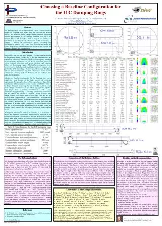
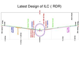
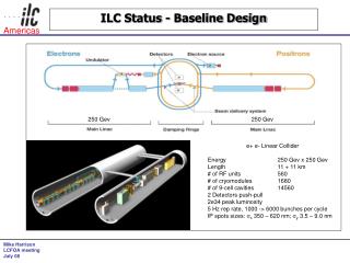
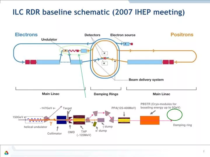
ILC RDR baseline schematic (2007 IHEP meeting). PBSTR (Cryo-modules for boosting energy up to 5GeV). PPA(125-400MeV). ~147GeV e-. Target. 150GeV e-. g. Damping ring. g dump. helical undulator. e- dump. TAP (~125MeV). OMD. Collimator. 2. Location of sources at the ILC.

E N D
ILC RDR baseline schematic (2007 IHEP meeting) PBSTR (Cryo-modules for boosting energy up to 5GeV) PPA(125-400MeV) ~147GeV e- Target 150GeV e- g Damping ring g dump helical undulator e- dump TAP (~125MeV) OMD Collimator 2
Location of sources at the ILC SB2009 and TDR RDR:
TDR Parameters: • Optimize the positron yields for known technologies: • Superconducting helical undulator. • Undulator parameter: K=0.92, lu=1.15cm, length reduced from 231m to 147m • Capturing magnets • Optical matching device: FC is now in TDR baseline instead of ¼ transformer • Targets: 0.4 X0 Ti, 1m diameter, 2000 RPM • Damping ring acceptance • Energy spread +/-0.5% => +/- 0.75% • emittance_x + emittance_y < 0.09 m-rademittance_x + emittance_y < 0.07m-rad • Goal: • Achieve yield of 1.5 positrons per electron in the drive beam. • 30%.
Status of the critical hardware components • 4 meter cryo-module, two 1.7m long RDR undulator. (Completed, STFC/RAL/Daresbury) • Target wheel prototype design and test. (Lancaster/Cockcroft/STFC/LLNL) • Rotating vacuum seal prototype test. (LLNL, Ongoing) • Capturing RF structure. (SLAC, Completed) • Flux Concentrator prototype design. (LLNL, New engineering design with water cooling) • New short period, high K undulator. (Cockcroft/STFC, ongoing), salc/micro=wave). • Remote handling/target removal engineering design (IHEP, almost done)
ILC Positron source optimization: Cases Studied: • Common Input Parameters: • Undulator parameter: K=0.92, lu=1.15cm • Target: 0.4 X0 Ti • Drift between undulator and target: 400m • Photon collimator: None • OMD: • Flux Concentrator Capturing (137 m long Undulator). • Quarter Wave Transformer Capturing (231 m long undulator). • Undulator Impacts on Drive Beam • Energy Spread and, • Emittance • Target Energy Deposition. • Path toward higher polarizations • Photon collimators
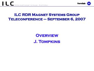
A pulsed flux concentrator • Pulsing the exterior coil enhances the magnetic field in the center. • Needs ~ 1ms pulse width flattop • Similar device built 40 years ago. Cryogenic nitrogen cooling of the concentrator plates.
Conditions • RF: 15MV/m for 1st meter and 8MV/m for the rest • OMD: FC, varying B0 with fixed length of 14cm • Capture evaluated at ~125MeV
Capture Efficiency for RDR Undulator with Different Drive Beam Energy
Capture Efficiency for 250 GeV Drive Beam with Different K of Undulators FC QWT
Yield and Pol 250GeV drive beam RDR with different drive beam
Explanation of Pol-B0 relation • As displayed in the plots, particles with lower energy tends to have bigger emitting angle and lower polarization. • When B0 get smaller, more lower energy particles will pass through the barrier created by the ramping up of B field and being captured. Meanwhile, more particles with higher energy but bigger angle will escape the capture as the field get weaker. That’s why lowering B0 will lower the polarization of captured beam initially. • When B0 get even smaller, the low energy and bigger emitting angle particles will escape the capture and then the captured positron beam polarization starts going up
RDR undulator, 250GeV60% Pol. possibility Yield Pol. With FC having B0 ~2.5T, 60% polarization and 1.5 yield can be achieved with photon collimator having an iris of ~0.55mm in radius using 231m RDR undulator
Yield Calculations Using RDR Undulator Parameters (137 meter and FC without photon collimators ) * No Quads misalignment included.
Emittance growth due to BPM to Quad misalignments-- From Jim Clark’s report
Beamline Lattice • New lattice design has been done to comply with the new layouts as follow.
Optics parameter of the new ILC positron source beamline lattice
Typical particle distribution at key points End of PTAPA End of PCAP End of PPA Before energy Compressor At the end of beamline, the treaty point to damping ring End of PTRANH
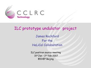
Shockwaves in the target SLC positron target after decommissioning S. Hesselbach, Durham • Energy deposition causes shockwaves in the material • If shock exceeds strain limit of material chunks can spall from the face • The SLC target showed spall damage after radiation damage had weakened the target material. • Initial calculations from LLNL had shown no problem in Titanium target • Two groups are trying to reconfirm result • FlexPDE (S. Hesselbach, Durham DESY) • ANSYS (L. Fernandez-Hernando, Daresbury) • No definitive results yet • Investigating possible shockwave experiments • FLASH(?) • https://znwiki3.ifh.de/LCpositrons/TargetShockWaveStudy 11/11/2010 JGronberg, LLNL Global Design Effort 21
Remote Handling Use detailed target, RF, etc model in Fluka – Andriy Confirmed by IHEP, China Model established –Jia/ IHEP Simple design, low cost. RH scenarios refined Changeover times (requirement ties in with lifetime of kit in RH), a day Replacement of pillow seals? Pillow seals need R&D Engineering design compatible with source layout – IHEP, XuejunJia
TeV upgrade scenarios • Scenarios has been Studied by both DESY and ANL • Proposed K=1, lu=4.3cm
Polarization upgrade • The lattice/layout of ILC positron source have left enough space for 231m effective undulator length • With the progress in FC prototyping at LLNL, only 147m long undulator will be needed to produce enough positron intensity without photon collimator. The extra space can be used for additional undulator modules for polarization upgrade • A multi stage photon collimator conceptual design for polarization upgrade has been done at DESY 24
Issues with ILC positron sources • Risk assessments for the e+ system: • Undulator (OK, more RD needed for different scenarios other than Baseline) • Photon Collimators (good progress made, conceptual design done, need a engineering design) • Capturing magnets (design done, prototyping done?) • Target (Tested, other engineering issues, OK) • Pre-accelerator (done) • RH (Engineering design done). • Lattice (Done). • Sources TeV upgrade seems to be OK.
Next for ILC, • TDR, almost done, will have a collaboration meeting this Friday to go through the write-up. • At next LCWS , Arlington in October, we will have the final version of TDR submitted. • Higgs factory source design…