Download
1 / 121
1.21k likes | 1.33k Views
End to End Security and Privacy in Distributed Systems and Cloud. Bharat Bhargava CERIAS Security Center CWSA Wireless Center Department of CS and ECE Purdue University bb@cs.purdue.edu Supported by NSF, AFRL, CISCO, Motorola, IBM. Visions of AF chief scientist ( Werner Dahm).

E N D
End to End Security and Privacy in Distributed Systems and Cloud Bharat Bhargava CERIAS Security Center CWSA Wireless Center Department of CS and ECE Purdue University bb@cs.purdue.edu Supported by NSF, AFRL, CISCO, Motorola, IBM
Visions of AF chief scientist ( Werner Dahm) • U.S Air Force “Technology Horizons” 2010--‐2030 http://www.aviationweek.com/media/pdf/Check6/USAF_Technology_Horizons_report.pdf • Next-Generation High-Bandwidth Secure Communications • Trusted, Adaptive, Flexibly-Autonomous Systems • New technologies for increased cyber resilience of Air Force networks and systems • Technologies can provide increased trust in autonomy to enable reduced manpower requirements via flexibly autonomous systems
PCA1: Inherently Intrusion-Resilient Cyber Systems • There will be an enduring need for technologies that can enable a wide range of Air Force capabilities that support missions, including better multi-level security solutions to facilitate sharing of information, systems, and training with international partners. • Command and Control Center (C2C), exploring solutions to national security problems with emphasis on improved information interoperability, systems integration, and cyber assurance, including net-centric strategies, complex systems engineering, and information technologies.
PCA2: Automated Cyber Vulnerability Assessments and Reactions • Ad hoc networks • Polymorphic networks • Agile networks • Complex adaptive distributed networks • Frequency-agile RF systems • V&V for complex adaptive systems • Autonomous systems • Collaborative/cooperative control • Information fusion and understanding • Cyber defense • Cyber resilience • Social network modeling
Objective • A trustworthy, secure, and privacy preserving network platform must be established for trusted collaboration in an End to End system. The fundamental research problems include: • Trust management • Privacy preserved collaborations • Dealing with a variety of attacks in networks • Intruder identification in ad hoc networks • Trust-based privacy preservation for peer-to-peer data sharing
Applications • Security sensitive applications in the next generation systems • Cloud Computing • Subscribe/Publish paradigm in DoD • Data sharing for medical research and treatment • Collaboration among government agencies for homeland security • Transportation system (security check during travel, hazardous material disposal) • Collaboration among government officials, law enforcement and security personnel, and health care facilities during bio-terrorism and other emergencies
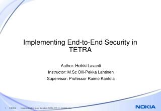
Fighter Satellites X-47B UCAS Seed Oppnet Radar Processing LCSs Carrier Merchant Ships Target USVs Underwater Acoustic Array The Oppnet Concept ( Navy STTR) Oppnets recruit and coordinate the capabilities of diverse networks, sensors, and computational resources in a way that optimizes resource utilization and also ensures improved QoS despite intermittent link connectivity. Oppnet links non-Oppnet UCAS links to Carrier
Before an Incident An Incident Occurs Arrival of Emergency Response Teams Forming Seed Oppnet Among Emergency Response Teams BuildingExpanded Oppnet: DiscoveringCandidate Helpers, Expanded Oppnet Overturned Vehicles (OnStar & BANs) Cellphone Tower Computer Network Road Infrastructure Sensors Selecting and IntegratingHelpers
Seek Collaboration with Faculty Interested in • Security/Privacy • Networking • Embedded Systems • Sensors • Distributed Systems • Assistive Technologies
Opportunistic Networks (with Navy) • Opportunistic Resource Utilization Networks (Oppnets) for UAV Ad-Hoc Networking: • Novel MANET consisting of an initial seed network that temporarily recruits resources. • Oppnets: • Allow the construction of highly adaptive, flexible, and maintainable application networks • Utilize and enhance applications, even including inflexible, stovepiped, legacy applications • Adapt and optimize the use of resources on-the-fly • Enable and facilitate distributed applications • Virtualize resources across platforms, allow scalability, and promote dynamic growth • Oppnets are: • Opportunistic resource/capability utilization networks • Opportunistic growth networks • Specialized Ad-Hoc Networks/Systems (SAHNS)
AFRL BAA Announcement • To support end to end authenticity, integrity and confidentiality within the AF, its mission capabilities must be preceded with strong 2-way authentication and authorization. • Currently available web browsers lack adequate support for standard Web Services programming models or protocols. This limitation presents the following challenges with the Air Force’s view of the architecture: • Authentication and authorization does not take place across intended end points. Such as between the requestor and provider. • Termination at intermediate steps of service execution exposes messages to hostile threats, for example, Man-in-the-Middle attacks. https://www.fbo.gov/index?s=opportunity&mode=form&tab=core&id=9c3333a8b3ee0f6d136e1dc6606ef0df&_cview=0
Aspects of Technical Approach ( AFRL Project) • Designed a policy-driven security architecture for SOA based across service domains • System provides a secure end-to-end message origin authentication for web service client requests and web service providers to ensure confidentiality and integrity in the presence of man-in-the-middle attacks. • Investigated adoption of web service WS-* standards (WS-Security, WS-Reliability, WS-Trust, WS-Interoperability) for enterprise Air Force systems. • Used Taint Analysis for monitoring security • A prototype implementation of proposed approaches based on open source technologies that integrated into existing government-off-the-shelf (GOTS) components in an operational environment. Developed prototype and conducted experiments in Cloud environment
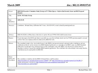
SOA Reference Scenario UDDI Registry request Forwarding the service list to Trust Broker and receive a ranked list Invoking a selected service Second invocation by service in domain A Invoking a service in public service domain End points (Reply to user)
Reference Scenario Details • Steps: • Global UDDI Registry request • User receives a list of services related to the requested category • User sends a refined list of services to Trust Broker module • Trust Broker categorizes the list of services and returns a classified list • Certified, Trusted, Untrusted services • Service Request • User selects a service based on its criteria (QoS, Trust category of service, Security preference, etc.) and invokes that service. • User creates a session with Trust Broker and selected service in Trusted Domain A. (Trust sessions are shown with dashed lines)
Reference Scenario Details (Cont.) • Trusted domain A will invoke another service in Trusted domain B. • Taint Analysis module will intercept the communications and reports any illegal external invocation • Trust session will be extended to this domain (a new trust link between domain A and trust broker) • Step four is repeated. • At this moment, an external service invocation to an public service is detected by Taint Analysis module • This will be reported to Trust Broker. Trust Broker will maintain the trustworthiness of this SOA service orchestration and if needed can stop it. • Service in service domain B invokes a service in an public (Maybe untrusted) domain C (Possibility of deploying Taint Analysis in this domain) • Service end points to user • The response of SOA invocation can be sent directly to the user
Detecting Service Violation in Internet • Problem statement Detecting service violation in networks is the procedure of identifying the misbehaviors of users or operations that do not adhere to network protocols. Collaboartion with Dr. Albert Legaspi Head, Networks DivisionSPAWARSYSCEN 55100, NAVY, San Diego
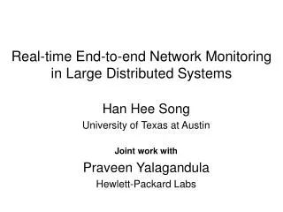
Topology Used (Internet) Victim, V A3 uses reflector H3 to attack V H5 A1 spoofs H5’s address to attack V
Detecting DoS Attacks in Internet *SPIE: Source Path Isolation Engine
Research Directions • Observe misbehavior flows through service level agreement (SLA) violation detection • Core-based loss • Stripe based probing • Overlay based monitoring
Approach • Develop low overhead and scalable monitoring techniques to detect service violations, bandwidth theft, and attacks. The monitor alerts against possible DoS attacks in early stage • Policy enforcement and controlling the suspected flows are needed to maintain confidence in the security and QoS of networks
Methods • Network tomography • Stripe based probing is used to infer individual link loss from edge-to-edge measurements • Overlay network is used to identify congested links by measuring loss of edge-to-edge paths • Transport layer flow characteristics are used to protect critical packets of a flow • Edge-to-edge mechanism is used to detect and control unresponsive flows
Monitoring Network Domains • Idea: • Excessive traffic changes internal characteristics inside a domain (high delay & loss, low throughput) • Monitor network domain for unusual patterns • If traffic is aggregating towards a domain (same IP prefix), probably an attack is coming • Measure delay, link loss, and throughput achieved by user inside a network domain Monitoring by periodic polling or deploying agents in high speed core routers put non-trivial overhead on them
Core-assisted loss measurements • Core reports to the monitor whenever packet drop exceeds a local threshold • Monitor computes the total drop for time interval t • If the total drop exceeds a global threshold a. The monitor sends a query to all edge routers requesting their current rates b. The monitor computes total incoming rate from all edge c. The monitor computes the loss ratio as the ratio of the dropped packets and the total incoming rate d. If the loss ratio exceeds the SLA loss ratio, a possible SLA violation is reported
Stripe Unicast Probing[Duffield et al., INFOCOM ’01]Idea from Butler Lampson and Howard Sturgis (Crash Recovery in a Distributed Data Storage System) • Back-to-back packets experience similar congestion in a queue with a high probability • Receiver observes the probes to correlate them for loss inference • Infer internal characteristics using topology • For general tree? Send stripe from root to every order-pair of leaves • Develop stripe-based monitoring by extending loss inference for multiple drop precedence
ZR1 ZR2 ZR1 U R2 Ak= Inferring Loss • Calculate how many packets are received by the two receivers. Transmission probability Ak where Zi binary variable which takes 1 when all packets reached their destination and 0 otherwise • Loss is 1 - Ak • For general tree, send stripe from root to every order-pair of leaves.
Overlay-based Monitoring • Problem statement • Given topology of a network domain, identify which links are congested • Solutions: Simple and Advanced methods • Monitor the network for link delay • If delayi > Thresholdidelay for path i, then probe the network for loss • If lossj > Thresholdjloss for any link j, then probe the network for throughput • If BWk > ThresholdkBW, flow k is violating service agreements by taking excess resources. Upon detection, we control the flows.
(a) Topology (b) Overlay (c) internal links Probing: Simple Method Congested link • Each peer probes both of its neighbors • Detect congested link in both directions
Experiments: Evaluation methodology • Simulation using ns-2 • Two topologies • C-C links, 20 Mbps • E-C links, 10 Mbps • Parameters • Number of flows order of thousands • Change life time of flows • Simulate attacks by varying traffic intensities and injecting traffic from multiple entry points • Output Parameters • delay, loss ratio, throughput Congested link Topology 1
Identified Congested Links Loss Ratio Loss Ratio Time (sec) Time (sec) (a) Counter clockwise probing (b) Clockwise probing Probe46 in graph (a) and Probe76 in graph (b) observe high losses, which means link C4 E6 is congested.
False Positive (theoretical analysis) • The simple method does not correctly label all links • The unsolved “good” links are considered bad hence false positive happens • Need to refine the solution Advanced Method
Example: if 100 links in the network and 20 of them are congested and 80 are “good”. The basic probing method can identify 15 congestion links and 70 good links. The other 15 are labeled as “unknown”. If all unknown links are treated as congested, 10 good link will be falsely labeled as congested. When the false positive is too high, the available paths that can be chosen by the routers are restricted, thus network performance is impacted.
Analyzing Simple Method • Lemma 1. If P and P’ are probe paths in the first and the second round of probing respectively, |P P’ |≤ 1 • Theorem 1.If only one probe path P is shown to be congested in any round of probing, the simple method successfully identifies status of each link in P • Performs better if edge-to-edge paths are congested • The average length of the probe paths in the Simple method is ≤ 4
Performance: Simple Method Theorem 2. Let p be the probability of a link being congested in any arbitrary overlay network. The simple method determines the status of any link of the topology with probability at least 2(1-p)4-(1-p)7+p(1-p)12 Detection Probability Frac of actual congested links
Advanced Method AdvancedMethod() begin Conduct Simple Method. E is the unsolved equation set for Each undecided variable Xij of E do node1 = FindNode(Tree T, vi, IN) node2 = FindNode(Tree T, vj , OUT) if node1 ≠ NULL AND node2 ≠ NULL then Probe(node1, node2). Update equation set E end if Stop if no more probe exists endfor end
Identifying Links: Advanced Method Loss Ratio Time (sec) Link E2 C2, C1 C3, C3 C4, and C4 E6 are congested. Simple method identifies all except E2 C2. Advanced method finds probe E5E1 to identify status of E2 C2.
Analyzing Advanced Method • Lemma 2.For an arbitrary overlay network with n edge routers, on the average a link lies on b = edge-to-edge paths • Lemma 3.For an arbitrary overlay network with n edge routers, the average length of all edge-to-edge paths is d = • Theorem 3.Let p be the probability of a link being congested. The advanced method can detect the status of a link with probability at least (1-(1-(1-p)d)b)
Bounds on Advanced Method • Graph shows lower and upper bounds • When congestion is ≤ 20%, links are identified with O(n) probes with probability ≥ 0.98 • Does not help if ≥ 60% links are congested Detection Probability Frac of actual congested links Advanced method uses output of simple method and topology to find a probe that can be used to identify status of an unsolved link in simple method
Experiments: Delay Measurements % of traffic Delay (ms) Cumulative distribution function (cdf) • Attack changes delay pattern in a network domain • We need to know the delay pattern when there is not attack
Experiments: Loss measurements Loss Ratio Loss Ratio Time (sec) Time (sec) (b) Stripe-based (a) Core-assisted Core-based measurement is more precise than stripe-based, however, it has high overhead
Attack Scenarios Delay (ms) Loss Ratio Time (sec) Time (sec) (a) Changing delay pattern due to attack (b) Changing loss pattern due to attack • Attack 1 violates SLA and causes 15-30% of packet loss • Attack 2 causes more than 35% of packet loss
Detecting DoS Attacks • If many flows aggregate towards a downstream domain, it might be a DoS attack on the domain • Analyze flows at exit routers of the congested links to identify misbehaving flows • Activate filters to control the suspected flows • Flow association with ingress routers • Egress routers can backtrack paths, and confirm entry points of suspected flows
Overhead comparison Communication overhead in KB Processing overhead (CPU cycle) Percentage of misbehaving flow Percentage of misbehaving flow (b) Communication overhead (a) Processing overhead • Core has relative low processing overhead • Overlay scheme has an edge over other two schemes
Observations • Stripe-based Monitoring • Stripe-based probing can monitor DiffServ networks only from the edges • It takes 10 sec to converge the inferred loss ratio to actual loss ratio with ≥ 90% accuracy • 10-15 delay probes and 20-25 loss probes per second are sufficient for monitoring • Probe is a 3-packet stripe • 3 shows good correlation, 4 does not add much
Observations (Cont’d) • Overlay-based Monitoring • Congestion status of individual links can be inferred from edge-to-edge measurements • When the network is ≤ 20% congested • Status of a link is identified with probability ≥ 0.98 • Requires O(n) probes, where n is the number of edge routers • Worst case is O(n2), whereas stripe-based requires O(n3) probes to achieve same functionality
Observations (Cont’d) • Analyze existing techniques to defeat DoS attacks • Marking has less overhead than Filtering, however, it is only a forensic method • Monitoring might have less processing overhead than marking or filtering, however, monitoring injects packets and others do not • Monitoring can alert against DoS attacks in early stage
Observations (Cont’d) • Traffic Conditioner • Using small state table, we can design scalable traffic conditioner • It can protect critical packets of a flow to improve application QoS (delay, throughput, response time, …) • Both Round trip time (RTT) & Retransmission time-out (RTO) are necessary to avoid RTT-bias among flows
Observations (Cont’d) • Flow Control • Network tomography is used to design edge-to-edge mechanism to detect & control unresponsive flows • QoS of adaptive flows improves significantly with flow control mechanism
Conclusion on Monitoring • Elegant way to use probability in inferring loss. 3-packets stripe shows good correlation • Monitoring network can detect service violation and bandwidth theft using measurements • Monitoring can detect DoS attacks in early stage. Filter can be used to stop the attacks • Overlay-based monitoring requires only O(n) probing with a very high probability, where n is the number of edge routers • Overlay-based monitoring has very low communication and processing overhead • Stripe-based inference is useful to annotate a topology tree with loss, delay, and bandwidth.