Download
1 / 10
100 likes | 107 Views
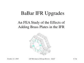
IFR detector mechanics. W. Baldini on behalf of the Ferrara IFR Group. XXVII SuperB Workshop and Kick off Meeting Isola d’Elba May 28 - June 02 2011. IFR Baseline Detection Technique. Plan to re-use BaBar IFR structure, adding iron to improve μ-ID

E N D
IFR detector mechanics W. Baldini on behalf of the Ferrara IFR Group XXVII SuperB Workshop and Kick off Meeting Isola d’Elba May 28 - June 02 2011
IFR Baseline Detection Technique • Plan to re-use BaBar IFR structure, adding iron to improve μ-ID • Extruded Scintillator as active material to cope with higher flux of particles • Minos-like scintillator bars readout through 3 WLS fibers and Silicon Photo-Multipliers (SiPM) • 82 or 92cm of Iron interleaved by 8-9 active layers (under study with simulations and testbeam) • Two readout options under study: • Time readout (TDC-RO) barrel • Binary readout (BI-RO) endcaps Minos like scintillator bar + WLS fibers SiPM
Readout Options • Time readout Option (TDC-RO): the hit bar gives the first coordinate while the signal arrival time provides the second • measure the 2 coordinate at the same time • 1ns time resolution ~ 20cm • need TDC readout for each channel • relatively simple to be constructed res~20cm • Binary readout Option: (BI-RO): the two coordinates are given by two planes of orthogonal scintillator bars: • high combinatorial • simpler (and cheaper) electronics • more complex construction Both option are being tested on beam thanks to a full depth prototype
Mechanics for the TDC Readout option • The baseline option for the Barrel is the TDC readout: • Outermost layer ≈ 400cm x 400cm • Innermost layer ≈ 200cm x 200cm • Scintillator bars 2x4x400 cm3 • 3 fibers each scint. bar • SiPM on both sides • The active material has to be protected and light shielded, keeping a max thickness of ≈ 23mm • For the innermost layers, due to the very high neutron flux, the SiPM will not be inside the module • Weight of a module 4m long and 10 scint. bars: ~ 40Kg, but not self sustaining • Proper moving/installing tools have to be built
Mechanics for the TDC Readout option • The basic idea is to prepare an aluminum box (0.5mm aluminum foil) • fix on it the scintillator bars (fibers already glued and polished) • Couple the fibers ( 5 cm longer than the scintillator) with the SiPM
Mechanics for the TDC Readout option • The PCBs supporting the SiPMs would be fixed on the bottom side of the box on a kind of “rail” • This to avoid too many holes in the box (to improve the light tightening) • The signal cables will be connected to the PCBs through 90° connectors • All the signal cables will be bundled and routed through a single hole (~ 10 cables) rail
Mechanics for the BI-RO Readout option Barrel • The mechanics for the BIRO option is more complex since the SiPMs cannot be simply put on scintillator’s ends (no space) • Two layers of orthogonal 1x4(?)x400 cm3 scintillators: • For the longitudinal scint. bars we can basically use the same technique as for the TDC option • For the orthogonal scint. Bars a special routing for the fibers has to be investigated • A first idea is to bring out the fibers orthogonally, in a large grove (≈2mm deep) which would house the fibers for the whole plane • The outermost layers could be made of 4 separated modules (to reduce fibers length) • The X and Y planes could be in separated modules (but the total thickness has to be < 23mm)
Mechanics of the Endcaps • For the endcaps the baseline option is the BIRO readout • mechanics is easier since there are less constraints • Here the modules are not rectangular so the aluminum boxes have to be properly shaped • Also here the issue willl be the shielding of the SiPM endcap Module 1 Module 1
Detector related Mechanical Activities • Aside to the active layer mechanics there are many other mechanical activities to be carried out • Tooling for the scintillator-fibers gluing (embedded holes or surface groves) • Given the non self sustaining structure of the active layers (aluminum foils very thin) a set of toolings have to be designed and built: • Supports to move the modules during the assembling and QC • Toolings for the movements and insertion of the modules in the flux return during the installation phase • Other tooling… • QC related toolings
Conclusions and next steps • The mechanics of the active layers is under definition • A present these are “conceptual” designs, we are now going through the details toward a “technical” design • Due to the high neutron flux an open issue is where to put the SiPMs of the innermost layers of the barrel • It would be desirable to put the SiPMs in accessible points, but this implies to use longer fibers… • We could consider the use of a few meters of clear fibers, in this case a proper coupling has to be done • Aside to the mechanics of the active layers there are all the tools for the moving, QC, and installation