Download

1 / 49
500 likes | 509 Views
Learn the basic rules of dimensioning and apply dimensions to objects according to engineering standards. Understand and define dimensioning terminology and recognize different machined holes.

E N D
Learning Objectives • Be able to understand the basic rules of dimensioning • Apply dimensions to objects in accordance with engineering standards • Define the following items: Dimension line, Extension line, Reference dimension, and Leader • Be able to recognize the following machined holes: Spotface, Counterbore, Countersink, & Depth.
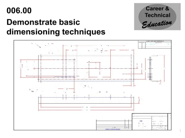
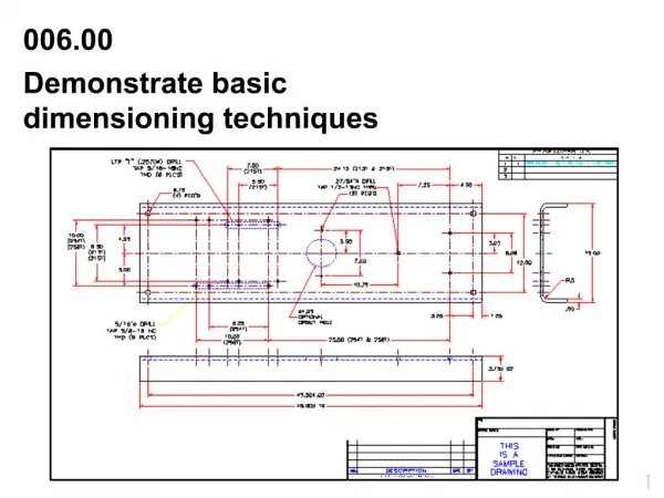
Basic Dimensioning • Dimensions allow a part to be manufactured – called a working drawing • Dimensions are ALWAYS in real world units • Dimensions should be applied in a concise, coherent manner (clear and concise)
Dimensioning Rules • Avoid placing any dimensions on the part (inside the view) unless there is no other option. • Avoid dimensioning to hidden features • Always place the dimension where the characteristic shape is shown in the most descriptive view. (This means don’t place a dimension on object lines making a “T joint”.) • Always dimension holes in their circular view by stating the diameter of drilled holes. Specify the hole depth of special features such as countersinking with a note following the dimension. • Dimension rounded corners and arc features as radii where they appear in their rounded views. • If the same value is repeated many times, then use a general note for the features. • Dimension cylindrical objects as diameters in their rectangular view. • Always place the first row of dimensions a minimum distance of 3 text heights away from the edge of the part. Additional stacks can be a minimum of 2 text heights away from each other. • Keep dimensions between the views whenever possible • Extension lines may cross each other and over other lines on the part, but dimension lines should never be crossed. • The overall dimension should always be given. It should be placed outside of smaller dimensions and be the furthest dimension from the part.
Dimensioning Rules continued… • Do not duplicate dimensions and avoid using unnecessary or superfluous dimensions • When all of the dimensions are expressed in inches, do not use inch mark (“) or the abbreviation for inches (in.) • For drawings dimensioned in inches, values less that one inch should not be preceded with a zero. • For metric drawings, omit the use of the millimeter (mm) notation following the numeral, as millimeters are the default units. • The origin for baseline or ordinate dimensions used as a datum should be extended from a finished edge of the part. • Conserve space and time by using abbreviations and standardized symbols whenever possible. • Reference dimensions should be placed in parentheses or should include the abbreviation “REF”. • Basic sizes (tolerance) should be placed inside a rectangular box • Extend leaders from the first of last word in a note. Point them toward the center of circular features that they are specifying. • Place dimensions among the various views to avoid crowding. Stagger horizontal dimensions to avoid contact or crowding of values.
Always place dimensions where the characteristic shape is shown in the most descriptive view
Always dimension holes in their circular view with the Ø. Specify special features (hole types) with a note. Also: Remember to locate hole position with ordinate dimensions to hole centers
Dimension rounded corners and arc features as radii where they appear in their rounded view.
If the same value is repeated many times, then use a general note for the feature. (ALL FILLETS AND ROUNDS ARE .125R)
Dimension cylinders in their rectangular view with a diameter symbol….Ø.
Place the first row of dimensions 3 text heights (3/8 ”or 10 mm) away from the edge of the part. Additional stacks of dimensions can be a minimum of two text heights (1/4 ”or 6 mm) away from each other
Extension lines may cross each other and over other lines on the part, but dimension lines should never be crossed. (Hint no “arrow-headed” lines can cross “arrow-headed” lines)
The overall dimension should always be given. It should be placed outside of smaller dimensions and be the farthest from the part.
Do not duplicate dimensions and avoid using unnecessary or superfluous dimensions
When all of the dimensions are expressed as inches. DO NOT use inch marks ('') or the abbreviation (.in)
For drawings dimensioned in inches, values less than 1 inch should not be proceeded with a zero.
For metric dimensions less than 1 mm DO place a zero in front of the decimal point.
For metric drawings, omit the use of the millimeter (mm) notation following the numeral, as millimeters are the default units.
The origin for baseline or ordinate dimensions used as a datum should be extended from a finished edge of the part.
Conserve space and time by using abbreviations and standardized symbols whenever possible.
Reference dimensions should be placed in parenthesis or should include the abbreviation “REF”. Basic sizes (tolerance) should be placed inside of a rectangular box
Extend leaders from the first or last word in a note. Point them toward (but not touch) the center of the circular features that they are specifying.
Place dimensions among the various views to avoid crowding. Stagger horizontal dimensions to avoid contact or crowding of the values
Angular features:Dimension angular features with either: X,Y coordinate location or Vertex location & degrees
Dimension Styles Aligned dimensions align with individual dimension lines. Unidirectional dimensions are read from the lower left corner of the sheet
Dimensioning in AutoCAD • AutoCAD does semi-automatic dimensioning • You select the features which should be dimensioned and the location for each dimension • AutoCAD measures the distance in question and applies the appropriate dimension complete with arrowheads, extension lines, and dimension lines
The Dimensioning Toolbar • The dimensioning commands can be easily accessed by: • Right Click on an existing toolbar and activate the dimensioning toolbar; • Or, From the “pull down” menu • View • Toolbars
Linear Dimensions • Linear dimensions are use to show basic dimensions of parts • They can be orientated either in a horizontal or vertical (or even aligned) fashion • AutoCAD will automatically measure the length specified and insert all the parts of the dimension.
Leaders • Leaders are used to apply thread notes and other annotations • Leaders begin at the arrow and continue from their elbow to their annotation • The annotation can be any text string you want to type
Radius and Diameter • By selecting a circular feature (arc or circle) with the Radius or Diameter option AutoCAD will measure the size and place the dimension at a user selected point • Using the Center option will place automatic centerlines on arcs or circles
Special Characters in AutoCAD: • %%c will show as the Diameter symbol: Ø • %%d will show as the Degree symbol: • %%p will show as the Plus-minus symbol: • %%u will start/stop text underlined • %%o will start/stop text overline
Spotfaced holes:No depth required. Cleans an uneven surface deep enough to allow full contact with bolt or washer.
Counterbore holesRequire both a diameter and a depth dimension.
Countersink holes: Used with flat head screws and bolts. They become flush when tightened. Used extensively in the aerospace industry. The 82 angle is common for cutting tools and screw threads
Chamfers: Break away sharp edges and help guide the part into a mating assembly. May be specified with one distance and one angle, or with two distances.
Necks: Necks are used for “O” ring seals, parts turned on lathes, and designed failure points
Knurls: Knurling is a process of rolling patterns onto cylindrical objects to make them easier to grip.
Repetitive features A combination of dimensioning & notes is used. A number in parenthesis indicates how many are required. The word TYPICAL (or TYP) indicates that all shown are the same.
Dimensioning Errors: • What is wrong with:
Dimensioning Errors: • What is wrong with:
Dimensioning Errors: • What is wrong with: