Download
1 / 54
540 likes | 548 Views
Explore the principles behind I/O hardware and software, including device controllers, memory-mapped I/O, and the communication between the CPU and I/O devices. Learn how to issue commands, handle interrupts and errors, and create device-independent interfaces.

E N D
Input/Output 5.1 Principles of I/O hardware 5.2 Principles of I/O software 5.3 I/O software layers 5.4 Disks Chapter 5
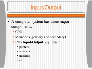
OS functions about I/O devices • Issue commands to the device • Catch interrupts • Handle errors • Provide easy-to-use interface between the devices and the rest of the OS • Ideally device independent
Principles of I/O hardware • Different people look at I/O hardware in different ways. • Electrical engineers look at chips, wires, power supplies, motors, and other physical components. • Programmers look at the interface presented to the software: commands, functions, reported errors • Our interest is restricted to how the hardware is programmed, not how it works inside.
I/O Devices • Two categories of I/O devices: • Block devices: (disk) • It stores information in fixed-size blocks, each one with its own address. It is possible to read or write each block independently. • Character devices: (printer, modem) • It delivers or accepts a stream of characters. It is not addressable and does not have any seek operation. • Some devices do not fit in the classification scheme. For example: clocks, memory-mapped screen. • The model of block and character devices is used as a basis for making I/O device software of OS device independent. For example, the file system deals just with abstract block devices and leaves the device-dependent part to the lower-level software.
Device Controllers • I/O devices consist of mechanical and electronic component • The electronic component is the device controller • On PC, it takes the form of a printed circuit card that can be inserted into an expansion slot • May be able to handle multiple devices • The interface between the controller and the device is often a very low-level interface • For example, a disk might be formatted with 256 sectors of 512 bytes per track. What actually comes off the drive is a serial bit stream, starting with a preamble, then the 4096 bits (512 bytes) in a sector, and finally an error-correcting code (ECC).
Device Controllers • Controllers jobs • Disk • Convert serial bit stream to blocks of bytes • Perform error correction if necessary • The block of bytes is typically first assembled in a buffer inside the controller. After its checksum has been verified, it can then be copied to main memory. • Monitor • Read bytes containing the character to be displayed from memory and generate the signals used to modulate the CRT beam to cause it to write on the screen. • The OS initializes the controller with a few parameters, such as the number of characters or pixels per line and number of lines per screen, and lets the controller take care of actually driving the beam.
Memory-Mapped I/O • Each controller has a few registers for communicating with the CPU. • By writing into these registers, the OS can command the device to deliver data, accept data, switch itself on/off, etc. • By reading from these registers, the OS can learn the device’s state, whether it is ready to accept a new command, etc. • Many devices have a data buffer that the OS can read and write. For example, video RAM.
Memory-Mapped I/O • How the CPU communicates with the control registers and the device data buffers? • Each control register is assigned an I/O port number. Using special I/O instructions like • IN REG, PORT • Compare IN R0, 4 with MOV R0, 4 for memory address • OUT PORT, REG • Map all the control registers into the memory space • Each control register is assigned a unique memory address to which no memory is assigned. (memory-mapped I/O) • Hybrid: Memory-mapped data buffers and separate I/O ports for the control registers. (Pentium)
Memory-Mapped I/O I/O ports (a) Separate I/O and memory space (b) Memory-mapped I/O (c) Hybrid
Memory-Mapped I/O • When the CPU wants to read a word, either from memory or an I/O port, • it puts the address on the bus’ address lines and then asserts a READ signal on a bus’ control line. • A second signal line is used to tell whether I/O space or memory space is needed. The corresponding unit then responds to the request. • For one address space (Fig 5-2(b)), every memory module and every I/O device compares the address lines to its servicing range. If (訂正) the address falls in its range, it responds to the request.
Memory-Mapped I/O • Comparison of memory-mapped I/O with special I/O ports: • For special I/O instruction, assembly codes are needed to access control registers. For memory-mapped I/O, control registers can be addressed in C the same as other variables. • With memory-mapped I/O, no special protection mechanism is needed to keep user processes from performing I/O. If each device has its control registers on a different page, the OS can give user control over specific devices by including the desired pages in its page table. Allow different device drivers to be placed in different address space. Not only reducing kernel size, but also keep the driver from interfering with others. • With memory-mapped I/O, every instruction that can reference memory can also reference control registers.
Memory-Mapped I/O • Disadvantage of memory-mapped I/O • Most computers have caching of memory words. Caching a device control register would be disastrous. The hardware has to be equipped with the ability to selectively disable caching on a per page basis. • If there is only one address space, then all memory modules and all I/O devices must examine all memory references to see which ones to respond to. • However, the trend is having a dedicated high-speed memory bus as shown in Fig 5-3(b). I/O devices have no way of seeing memory addresses as they go by the memory bus, so they have no way of responding.
Memory-Mapped I/O A single-bus architecture A dual-bus memory architecture
Memory-Mapped I/O • First possible design: first send all memory references to the memory. If the memory fails to respond, then CPU tries the other buses. • Second possible design: put a snooping (窺探) device on the memory bus to pass all addresses to potentially interested I/O devices. • Third possible design: like the one used in Pentium (Figure 1-11), filter addresses in the PCI bridge chip. This chip contains range registers that are preloaded at boot time. Addresses that fall within one of the ranges marked as nonmemory are forwarded onto the PCI bus instead of memory. The disadvantage is the need for figuring out at boot time which memory addresses are not really memory addresses.
Direct Memory Access Operation of a DMA transfer, the DMA controller has access to the system bus independent of the CPU
Direct Memory Access Step 1: The CPU programs the DMA controller by setting its registers so it knows what to transfer where. It also issues a command to the disk controller telling to read data from the disk into its internal buffer and verify its checksum. When valid data are in the disk controller’s buffer, DMA can begin. Step 2: The DMA controller initiates the transfer by issuing a read request over the bus to the disk controller. Step 3: Data are written to memory. Step 4: When the write is complete, the disk controller sends an acknowledge signal to the DMA (p 277 訂正) controller over the bus. The DMA controller then increments the memory address and decrements the byte count. Repeat steps 2 to 4 until the byte count reaches 0. Then, the DMA controller interrupts the CPU to let it know the transfer is complete.
Direct Memory Access • More complex DMA controllers can be programmed to handle multiple transfers at once. • Some DMA controllers can operate in word-at-a-time and block mode. • Word-at-a-time mode: the DMA controller requests for the transfer of one word and gets it. If the CPU also wants the bus, it has to wait. This mechanism is called cycle stealing because the device controller sneaks in and steals an occasional bus cycle from the CPU. • Block mode: the DMA controller tells the device to acquire the bus, issue a series of transfers, then release the bus. This is called burst mode. It can block the CPU and other devices for a substantial period if a long burst is being transferred.
Direct Memory Access • The above discussed model is called fly-by mode, the DMA controller tells the device controller to transfer the data directly to main memory. • An alternative mode is to have the device controller send the word to the DMA controller, which then issues a second bus request to write the word to wherever it is supposed to go. It is more flexible in that it can also perform device-to-device copies and even memory-to-memory copies.
Direct Memory Access • Why does not the controller just store the bytes in main memory as soon as it gets them from disk? Why does it need an internal buffer? • The disk controller can verify the checksum before starting a transfer. If the checksum is incorrect, an error is signaled and no transfer is done. • Once a disk transfer has started, the bits keep arriving from the disk at a constant rate, whether the controller is ready for them or not. • If the controller tried to write directly to memory, it would have to go over the system for every word transferred. If the bus were very busy, the controller might end up storing quite a few words and having a lot of administration to do as well. • When the block is buffered internally, the bus is not needed until the DMA begins, so the design of the controller is much simpler. • Not all computers use DMA because the CPU is often far faster than the DMA controller and can do the job much faster. Also, getting rid of DMA controller saves money.
Interrupts Revisited (5.1.5, p279—280 上半) How an interrupts happens. Connections between devices and interrupt controller actually use interrupt lines on the bus rather than dedicated wires Bus
Interrupts Revisited • When an I/O device has finished the work given to it, it causes an interrupt. It does this by asserting a signal on a bus line that it has been assigned. This signal is then detected by the interrupt controller chip on the parentboard, which then decides what to do. • If no other interrupts are pending, the interrupt controller processes the interrupt immediately. Otherwise, the device is just ignored for the moment. In this case, it continues to assert an interrupt signal on the bus until it is serviced by the CPU. • To handle the interrupt, the controller puts a number on the address lines specifying which device wants attention and asserts a signal that interrupts the CPU.
Interrupts Revisited • The interrupt signal causes the CPU to stop what it is doing and start doing something else. The number on the address line is used as an index into the interrupt vector to fetch a new program counter, which points to the start of the corresponding interrupt service procedure. • Shortly after it starts running, the interrupt service procedure acknowledges the interrupt by writing a certain value to one of the interrupt controller’s I/O ports, so that the controller now is free to issue another interrupt. By having the CPU delay this acknowledgement until it is ready to handle the next interrupt, race conditions involving multiple simultaneous interrupts can be avoided.
Interrupts Revisited • Further issues: • Before starting the service procedure, which information is saved and where it is saved? • In pipelined/superscalar systems, when the interrupt occurs, the program counter may not reflect the correct boundary between executed and non-executed instructions. Skip p 280 下半至 282
5.2 Goals of the I/O Software • Concepts in the design of I/O software • Device independence • programs can access any I/O device without specifying device in advance. Ex., read a file from floppy, hard drive, or CD-ROM • Uniform naming • name of a file or device should be a string or an integer, and not depend on the device. Ex., all files and devices are addressed by a path name • Error handling • Errors handled as close to the hardware as possible • The upper layers should be told about an error only if the lower layers are not able to deal with the problem
Goals of the I/O Software • Synchronous vs. asynchronous transfers • blocked transfers (easy to program) vs. interrupt-driven (most physical I/O is asynchronous) • Buffering • Often data coming off a device cannot be stored in its final destination. Ex: packets off the network. • Some devices have severe real-time constraints, so the data must be put into the output buffer in advance to avoid buffer under-runs (缺貨). • Involves considerable copying and has a major impact on I/O performance • Sharable vs. dedicated devices • Some devices, like disks, are sharable • Some devices, like tape drives, should be dedicated • Dedicated devices introduces a variety of problems, such as deadlocks
Programmed I/O • Three ways to perform I/O: • Programmed I/O, • interrupt-driven I/O, • I/O using DMA • Programmed I/O: • Have the CPU do all the work
Programmed I/O Steps in printing a string
Programmed I/O • First assembles the string in a buffer in the user space • The user process then acquires the printer by making a system call to open it. • The OS then copies the buffer with the string to an array, say p, in the kernel space. As soon as the printer is available, the OS copies the first character to the printer’s data register, in this case using memory-mapped I/O. • After that, the OS checks to see if the printer is ready to accept another one. The printer indicates its availability by setting some bit in its status register or putting some value in it. • The OS now waits for the printer to become ready again. When that happened, it prints the next character. This loop continues until the entire string has been printed. Then control returns to the user process.
Programmed I/O Writing a string to the printer using programmed I/O. After outputting a character, the CPU continuously polls the device to see if it is ready to accept another. This is called polling or busy waiting. However, each character takes about 10 ms to print. It is simple, but tied up the CPU till I/O is done
Interrupt-Driven I/O Writing a string to the printer using interrupt-driven I/O (a) Code executed when print system call is made (b)Interrupt service procedure
Interrupt-Driven I/O • When the printer has printed the character and is prepared to accept the next one, it generates an interrupt. The interrupt stops the current process and saves its state. Then the printer interrupt service procedure is run. • Disadvantage: an interrupt occurs on every character
I/O Using DMA(Direct Memory Access) Idea: let the DMA controller feed the character to the printer one at a time, without the CPU being bothered. Reduce the number of interrupts from one per character to one per buffer (a) code executed when the print system call is made (b)interrupt service procedure If DMA is not capable of driving the device at full speed or the CPU has nothing to do while waiting for the DMA interrupt, then interrupt-driven I/O or programmed I/O may be better.
I/O Software Layers Layers of the I/O Software System
Interrupt Handlers • Interrupt handlers are best hidden • have driver starting an I/O operation block until I/O has completed and the interrupt occurs. Like doing a down on a semaphore, a wait on a condition variable, or a receive on a message. • Then the interrupt procedure does its task to handle the interrupt • Then the interrupt procedure unblocks the driver that started it (like an up on a semaphore) • This models works best if drivers are structured as kernel processes, with their own states, stacks, and program counters.
Interrupt Handlers • Steps must be performed in software after the hardware interrupt has completed • Save any registers (like PSW) not already saved by the interrupt hardware • Set up a context for the interrupt service procedure (TLB, MMU, page tables) • Set up a stack for the interrupt service procedure • Acknowledge the interrupt controller. If there is no centralized interrupt controller, reenable interrupts • Copy the registers from where they were saved to the process table
Interrupt Handlers • Run the interrupt service procedure. It will extract info from the interrupting device controller’s registers • Choose which process to run next. If the interrupt has caused some high-priority process that was blocked to become ready, it may be chosen to run now. • Set up the MMU context for the process to run next. Some TLB set up may be needed. • Load new process' registers, including PSW • Start running the new process
Device Drivers • The number of device registers and the nature of commands vary radically. Ex: mouse driver has to accept information about how far the mouse has moved and which button are currently pressed. What information does a disk driver need? • Each I/O device needs some device-specific code for controlling it. This code, called device driver, is generally written by the device’s manufacturer and delivered along with the device for each OS.
Device Drivers • Each device driver normally handles one device type, at most, one class of closed related devices. Ex: SCSI disk driver. • In order to access the device’s hardware, meaning the controller’s registers, the device driver normally has to be part of the OS kernel. • The designer of the architecture of OS needs to have a well-defined model of what a driver does and how it interacts with the rest of the OS.
Device Drivers Logical position of device drivers is shown here. In reality all communication between drivers and device controllers goes over the bus.
Device Drivers • Device driver categories • Block device: Read a block for block device • Character device: Write a character string for character device • In Unix, OS is a single binary program that contains all of the drivers that it will need compiled into it. • In PC, starting with MS-DOS, drivers were dynamically loaded into the system during execution
Device Drivers • Device driver functions: • Accept abstract read and write requests and see that they are carried out. • Initialize the device, if needed • Manage power requirement • log events
Device Drivers • General structure of device driver program • Checking whether input parameters are valid • If yes, a translation from abstract to concrete terms may be needed • If not, an error is returned • Check if the device is currently in use • If yes, the request is queued for later processing • If no, check hardware status to see if the request could be handled now • It may be necessary to switch the device on or start a motor before transfers can be begun. Once the device is on and ready to go, the actual control can begin
Device Driver • After the driver knows which command it is going to issue, the driver • Write commands into the controller’s device registers. Check to see if the controller accepted the command and is prepared to accept the next one • After the commands have been issued, two cases: • Wait until the controller does some work for it, so it blocks itself until the interrupt comes in to unblock it • The operation finishes with no delay, like scrolling the screen in the character mode • After the operation has been completed, check for errors and If OK, the driver may have data to pass to the device-independent software. • Finally, it returns status info to its caller. • If other requests are queued, one of them will be selected and started. Otherwise, the driver blocks waiting for the next request.
Device Drivers Other issues • An I/O device may complete while a driver is running, interrupting the driver. Ex: while the network driver is processing an incoming packet, another packet may arrive. Drivers have to be reentrant, meaning a running driver has to expect that it will be called a second time before the first call has completed. • Handle hot pluggable system: • When the user suddenly removed a device from the system, not only must the current I/O be aborted, but pending requests for that device must be gracefully removed from the system. • Unexpected adding of new devices may cause the kernel to juggle resources (如:interrupt request lines) • Drivers may need to call certain kernel procedures • Ex: to manage MMU, timer, DMA controller, interrupt controller, etc.
Device-Independent I/O Software Make all I/O devices and drivers look the same Functions of the device-independent I/O software
Uniform Interface for Device Drivers (a) Without a standard driver interface (b) With a standard driver interface
Uniform Interface for Device Drivers • Issues • The interface between the device drivers and the rest of the OS • How I/O devices are named: mapping symbolic device names onto the proper driver. In I-node of UNIX, • major device number to locate the driver, • minor device number to specify the unit to the read or written • Protection: how does the system prevent users from accessing devices that they are not entitled to use. Usual protection rules for files also apply to I/O devices
Buffering (a) Unbuffered input: each arriving character causes an interrupt (b) Buffering in user space: problem: what happens if the buffer is paged out when a character arrives? (c) Buffering in the kernel followed by copying to user space: problem: what happens to characters that arrive while the page with the user buffer is being brought in from the disk? (d) Double buffering in the kernel: while one is being copied to user space, the other is accumulating input. Output buffer? Use (c) 但方向要相反