Download
1 / 46
460 likes | 466 Views
Software Systems Geared Towards Evolution of Next Generation Airport Tower Control. 2008 Demonstration of Integrated Display, Video and Multilateration at Syracuse Hancock Int’l Airport (SYR). Wednesday, July 8, 2009. Seminar Agenda. Aspen Tower Operational Issue Solution Concept

E N D
Software Systems Geared Towards Evolution of Next Generation Airport Tower Control 2008 Demonstration of Integrated Display, Video and Multilateration at Syracuse Hancock Int’l Airport (SYR) Wednesday, July 8, 2009
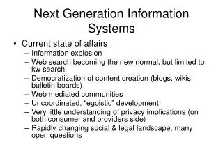
Seminar Agenda • Aspen Tower Operational Issue • Solution Concept • ASDE-X System • INTELLIDAR System • Prototype Display System • Syracuse Hancock Airport Demonstration System • Schedule: Concept to Demonstration • Demonstration System Architecture
Aspen Tower Operational Issue • Single Runway Airport in Mountainous Terrain • Planned 1000 foot runway extension • Not visible from the Air Traffic Control Tower even with binoculars • Positive control requires visibility of runway queue/runway threshold
Inside an Air Traffic Control Tower • Visibility often limited • Runway queues may be 2 or more miles from tower cab • Technology Used to Add Situational Awareness • Traditional “Birds Eye View”
Solution Concept • Sensis ASDE-X System + • Searidge Intellidar System + • Prototype Integrated Display = • Display presentation of detected, identified, aircraft
Sensors • Cooperative Sensors • Rely on periodic aircraft transponder transmissions: “Here I am” (roughly once per second) • Most transponders do not transmit position, only “presence/identity” • Non-Cooperative Sensors • Transmit a “probe signal” and detect “skin-paint reflections”
ASDE-X System • Multi-sensor system (cooperative and non-cooperative sensors) • Multilateration (surface to ~15000 ft, out to ~7nmi): coop • Terminal Radar (~1000 ft to ~40000 ft, out to 60 nmi): coop and non-coop • Surface Movement Radar (surface only): non-coop • Detection, positioning, tracking, and fusion algorithms • Fused per-aircraft “tracks” are formed containing position, identity, and other state information
SMR Antenna/Pedestal MLAT Remote Unit (RU) Site ASDE-X On-Airfield System Components
INTELLIDAR System • Two or more video cameras • Video detection processing (“bounding box processing”) • Digitization/Positioning (“plot generation”) • Analog imagery, bounding boxes with Id, digitized plot output
Sample Camera Deployments Camera Sensors Deployed on Glide Slope Masts AUH Deployment
Video Processing Architecture • Cameras deployed in critical areas around airport to provide continuous monitoring • Captured video streams processed by Imaging platform • Detected objects positioned with real-world geographical coordinate information • Radar-like target data: • Target coordinates, speed, heading and shape • Presented on custom GUI display • Can be fused with existing ATC systems
Digital Camera Selection Trades • Camera selection driven by… • Size of tracked objects • Day vs. night operations
Communication Bandwidth Trades • Communications infrastructure dependent on required… • Video refresh rate, and resolution • Airport infrastructure
Prototype Display System • Pluggable Display Architecture • 3-D Scene Graph • Full earth world model • WGS-84 Reference Frame • Pluggable satellite imagery • Pluggable “local” models • Wide area, and local area surveillance views
Prototype Integrated Display Features • Plan View • MLAT + Video targets • Aircraft data block • Video Inset… target video + “bounding box” • Video target correlated with • Selected video correlated with MLAT target flashed in video view
Syracuse Hancock Airport Demonstration System Integration and Demonstration Facility Mlat Sensor Dual Video Camera, Intellidar, Mlat Sensor Site Mlat Sensor Mlat Sensor
Schedule: Concept to Demonstration • Demonstration Opportunity Realized on June 11, • Demonstration date August 28 • No possibility to “slip to the right” • Plan allowed little, if any, room for problems
Schedule Concept to Demonstration (cont.) • Coordination • ATIS NOTAM (“Notice to Airmen: Leave your transponders on”) • Hardware acquisition • Software development • Site installation/Integration • Facility Integration • Core Team • Sensis (1 software, 1 systems, 1 tech lead, 1 business lead) • Searidge (2 software, 1 tech lead, 1 business lead) • Extended Team • A variety of additional people required to support various activities
Demonstration Overview • FAA ICDLS ASDE-X infrastructure • 5-RU MLAT system to track transponder-equipped aircraft on RWY 28 and adjacent taxiways • FAA flight plan interface for flight IDs • SMR and data fusion not invoked • Searidge Technologies’ IntelliDAR video system • Deployed to cover approach end of RWY 28 and TWY A • Detects aircraft and vehicles within field of view • Provides data feed containing position and “bounding box” of each tracked target • Three demonstration displays • Certified ASDE-X Tower Display • Standalone Camera Display • Prototype Integrated Tower Display
Demonstration Overview (cont.) • Wireless 802.11 (relatively “skinny” pipe, commercial band) • Focus on pre-recorded data and the collection/playback of “demonstration scenarios” • Not reliant on “targets of opportunity”
Demonstration System Architecture • ASDE-X ICDLS system • Remote Unit (RU) and Reference Transmitter (RefTran) sites • Processing… MLAT and display • ATC Tower Display • SMR not enabled • Searidge cameras Co-located with RU • Three displays options • ASDE-X tower display… MLAT • IntelliDAR display… video • Prototype display… integrated surveillance
Camera Coverage at “Greenfield Site” • Two IntelliDAR cameras on ASDE-X RU antenna mast • IntelliDAR PC in RU outside enclosure • Wireless data link to ASDE-X facility
Display Design Decisions • Display built on a full-earth WGS-84 world model • Allows for visualization of global and/or local (e.g. airport) features • Display supports overlay of informational “Views” • Some elements built into the core, others plugged in on the fly • Support built-in “birds eye view” of “tracked targets” within a local or global area
Display Design Decisions (Pluggability) • Pluggable Architecture • Plugins loaded as DLL’s on startup • Plugins may or may not have a visual component • Plugins may leverage • Pluggable View API • Pluggable Configuration API • Pluggable “to-scale” world and local models
Display Design Decisions (Leverage Open Source) • Leverage platform independent, open source where possible • Linux/Windows/Macintosh • Direct 3D, OpenGL • Rendering Architecture Leverages a 3D Scene Graph • OGRE (Object Oriented Graphics Rendering Engine) • www.ogre3d.org • User Interface Architecture implemented using “Crazy Eddies GUI” (CEGUI) • www.cegui.org.uk
Display Design Decisions(Production Pipeline) • Display production pipeline similar to the production pipeline implemented by game companies • Modeler (e.g. 3D-Studio Max) may be used to model world elements that can be plugged in to the world model. • Example we often take Autocad files (DXF format) which provide a “to-scale” model of an airport into a modler, skin it, then load it at run-time
Intellidar Plugin Design Decisions • Leverage the Component Plugin API to register with the application on startup • Leverage the View Plugin API to render “real-time” imagery • The real-time view will be overlaid with icons representing “snapshots in time” (one per configurable time period) • User will be able to click on a snapshot to see a full-screen view of the field of view at that time • Plugin will display “target plots” on the “birds eye view”
Intellidar Plugin Design Decisions (cont.) • Leverage the Actor Plugin API to allow target plots to be fed to the birds-eye view, and to allow for events on an identified actor to be fed to the intellidar plugin. • Display “target bounding boxes” overlaid on real-time imagery • Allow user to click on bounding box and highlight corresponding target in “birds eye view”. • Allow user to click on target in “birds eye view” and highlight corresponding bounding box • Leverage the Style Manager/Editor Plugin API to allow for user configurability of the displayed Intellidar targets/video
Intellidar Plugin Design Decisions (cont.) • Boost C++ Libraries • ASIO Networking (Asynchronous IO) • Shared Pointers (Memory Management) • www.boost.org
Intellidar Plugin Video View Overlaid on “Birds Eye View” “Birds Eye View” of the Airport Surface Intellidar Plugin Video View ASDE-X Target Intellidar Target Intellidar Target “Bounding Box”
Intellidar Plugin Video View Overlaid on “Birds Eye View” (cont.) Command Bar Perspective Selection Video Plugin Image Browser Plugin Intellidar Plugin Video View “Historical Snapshot”
Intellidar Plugin Configuration Menu Intellidar Plugin Configuration Tab Plugged in To Application Configuration Editor
Intellidar Plugin Historical Snapshot Displayed in response to a “user-click” on one of the history icons
Other Application Plugins Displayed in response to a “user-click” on an icon within the Image Browser Plugin Camera/Intellidar “Greenfield Site” Location
Intellidar Plugin Main Thread • Initialize threads • Establish communications framework • Poll CDA and CORE interface threads to get messages in queue • Runtime Distribution of “Target Updates” to built-in Birds Eye View • Implement “per-site received Image registry” • Runtime distribution of received images to registered clients • Acts as an “Actor Generator” within the Actor Plugin API • ASTERIX data (CORE messages) decoded and used to generate Actor updates • JPEG data + Bounding Box data (CDA messages) decoded stored in the “per-site” image map
Intellidar CDA Interface Thread • Leverages, slaved to, “IO Service” thread • TCP client connects to CDA • TCP retries implemented • Byte oriented message protocol (framing required) • Rx message queue retained until “Getter” empties queue • Shared pointers leveraged for speed • Overflow (load shed) handling • Semaphores used to synchronize access to messages from the queue.
Intellidar Core Interface Thread • Leverages, slaved to, “IO Service” thread • UDP Listener • Packaged Message Protocol • Rx messages retained in queue until “Getter” empties queue • Shared pointers leveraged for speed • Overflow (load shed) handling • Semaphores used to synchronize access to messages from the queue.
Intellidar Image Display • Per the View Plugin API IntellidarView acts as a “View Decorator” • 3 or 4 JPEG Images displayed each second • Register image client with main Intellidar thread. Registry based on “view perspective” • Intellidar Controller polls for image data associated with “view perspective”. • The view perspective is tied to a given intellidar site. • IntellidarController acts as an “Actor Event Listener” according to the Actor Plugin API • Intellidar Controller acts as an “App View Controller” according to the View Plugin API. Keyboard/Mouse events, mapped to registered functions, and routed to controller. • Snapshot history and target bounding boxes overlaid on displayed Image
Intellidar Display Configuration • IntellidarConfig Manager acts as a “Style Manager Module” according to the Style Manager/Editor API • IntellidarCfg Editor acts as a “Style Editor Module” according to the Style Manager/Editor API • Listeners installed to detect user-initiated change of configuration • User-initiated configuration changes delivered to IntellidarConfig Manager which then drives updates of the displayed information