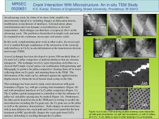
Download
1 / 4
40 likes | 168 Views
Identifying Critical Interfaces In Fuel Cell Electrodes Scott Barnett & Peter Voorhees, Northwestern University, DMR 0542740 Katsuyo Thornton, Univ Michigan, DMR 0542874 Stuart Adler, Univ Washington, DMR 0542619.

E N D
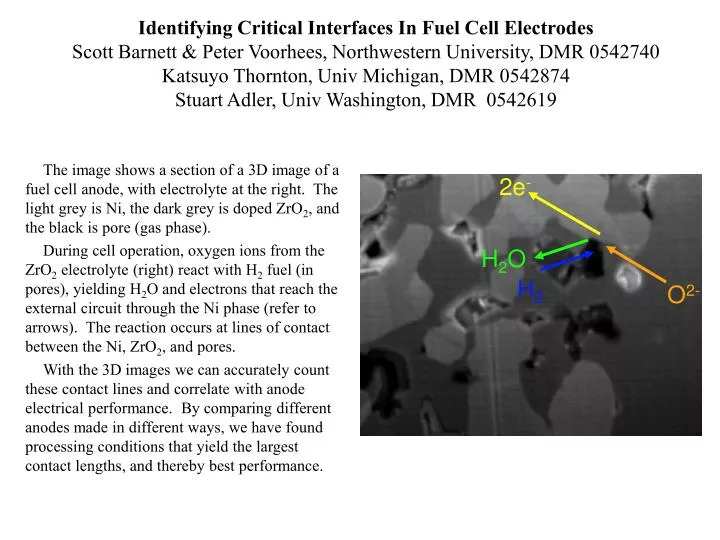
Identifying Critical Interfaces In Fuel Cell ElectrodesScott Barnett & Peter Voorhees, Northwestern University, DMR 0542740Katsuyo Thornton, Univ Michigan, DMR 0542874Stuart Adler, Univ Washington, DMR 0542619 The image shows a section of a 3D image of a fuel cell anode, with electrolyte at the right. The light grey is Ni, the dark grey is doped ZrO2, and the black is pore (gas phase). During cell operation, oxygen ions from the ZrO2 electrolyte (right) react with H2 fuel (in pores), yielding H2O and electrons that reach the external circuit through the Ni phase (refer to arrows). The reaction occurs at lines of contact between the Ni, ZrO2, and pores. With the 3D images we can accurately count these contact lines and correlate with anode electrical performance. By comparing different anodes made in different ways, we have found processing conditions that yield the largest contact lengths, and thereby best performance. 2e- H2O H2 O2- 2mm
Identifying Critical Interfaces In Fuel Cell ElectrodesBroader Impacts Scott Barnett & Peter Voorhees, Northwestern Univ, DMR 0542740 The picture shows a high school teacher, Sherri Rukes, who worked at Northwestern University over the summer measuring electrical properties of fuel cell electrodes on the above-described project. We also worked with Sherri on fuel cell demonstrations that she will use in her Chemistry classes this year - our group will supply the fuel cells and is helping Sherri develop science/technology points to go with the demonstration.
Predicting Stability of Fuel Cell ElectrodesScott Barnett & Peter Voorhees, Northwestern Univ, DMR 0542740Katsuyo Thornton, Univ Michigan, DMR 0542874Stuart Adler, Univ Washington, DMR 0542619 Our project has focused on using advanced microscopy tools to observe key microstructural features in fuel cells. The image at top left shows such an image of the “triple-phase boundary” (TPB) lines, sites where electrochemical reactions occur, in a Ni-YSZ anode. We have used the 3D images as a starting point for predicting how the microstructure, including TPB lines, evolves with time. This has important implications for long-term device stability. The image at bottom right shows the predicted the boundary lines after long-term operation - the decrease in overall line length allows us to predict the expected change in fuel cell performance. In the future, we will be able to find microstructures that improve stability.
Predicting Stability of Fuel Cell Electrodes:Broader Impacts Scott Barnett & Peter Voorhees, Northwestern Univ, DMR 0542740 The image shows an artists depiction of a planned “Vision 21” power plant that will utilize solid oxide fuel cell technology to improve efficiency, reduce emissions, and help to make CO2 sequestration feasible. The issue of long-term stability addressed in this research is critical to make fuel cells that can work reliably for planned power plant lifetimes.


![[Ca 2+ ]ext (1000 m M)](https://cdn1.slideserve.com/3303376/slide1-dt.jpg)