Download
1 / 7
70 likes | 204 Views
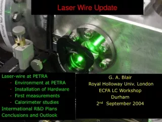
CALICE pixel Laser testing update. Black cylinder. Laser MIP equivalent calibration update Si detector coupled to low noise CA + differentiator (no shaper) Amplifier Gain measured ~ 7mV/MIP (c.a. 3 times lower than nominal value, confirmed with manufacturer)

E N D
CALICE pixel Laser testing update Black cylinder • Laser MIP equivalent calibration update • Si detector coupled to low noise CA + differentiator (no shaper) • Amplifier Gain measured ~ 7mV/MIP (c.a. 3 times lower than nominal value, confirmed with manufacturer) • Amount of stray light reduced by using a small dark cylinder around the sensor G.Villani Aug. 07
CALICE pixel Laser testing A250CF calibration using injected charge through capacitor and pulse generator Q(fC)=((2.6566+/-0.3)/3.25+V/3.25-1)*3.2 noise signal MIP charge signal G.Villani Aug. 07
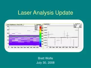
CALICE pixel Laser testing Laser output measurement - Vout vs % intensity. Laser output 0% Laser output 100% G.Villani Aug. 07
CALICE pixel Laser testing Q in S3590-A MIP ‘noise’ Q generated vs % laser intensity – MIP- eqv generated vs % laser intensity with EMI and amplifier noise quadrature-subtracted MIP-eqv calibration accurate to +/-15% G.Villani Aug. 07
CALICE pixel Laser testing ND filters for different MIP ranges Sensor housing • Next step: • Refined calibration using non coated sensor and thru-hole sensor housing • (back scattered light, non uniformity of thickness) • Study of laser temporal profile (for deconvolution of sensor response) • Comparison of Laser signal with radiation source signal • Calibration using different MIP ranges • SW control from DAQ G.Villani Aug. 07
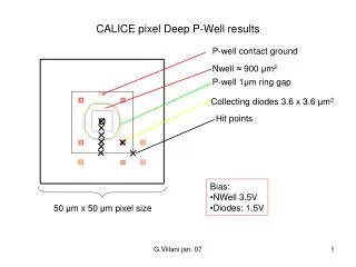
S1 CALICE pixel Deep P-Well simulation 3D simulation of final layout with all around DPW ∆Q ~ 10% @ 2.2*105 points c.a. 40 hits points simulated G.Villani Aug. 07
CALICE pixel summary Conclusions • Laser sub-MIP calibration accomplished: further refinement and verifications ongoing • Full pixel simulation with final layout ongoing G.Villani Aug. 07