Download
1 / 17
170 likes | 302 Views
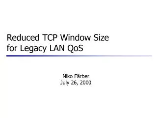
Reduced TCP Window Size for VoIP in Legacy LAN Environments. Nikolaus F ä rber, Bernd Girod, Balaji Prabhakar. Scenario. Host. SOHO with < 30 nodes Switched, full duplex LAN architecture 10/100 BASE-T, single switch. 10 BASE-T. S. T1/DSL/Cable. R. WAN. IP Phone. T2.

E N D
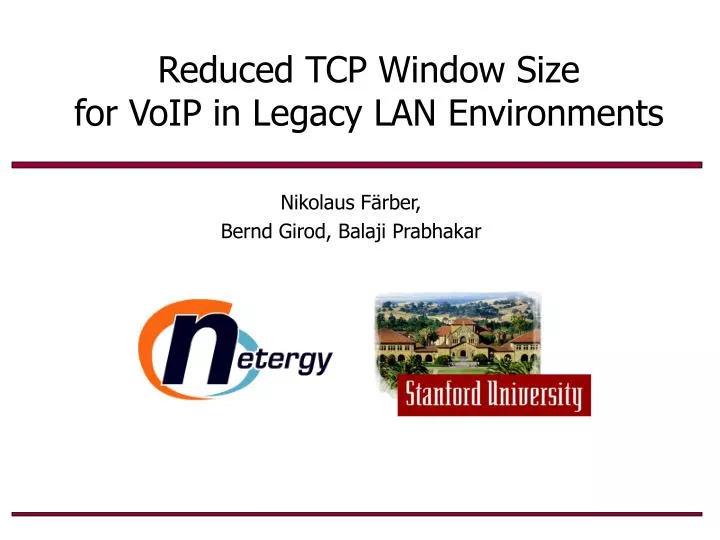
Reduced TCP Window Sizefor VoIP in Legacy LAN Environments Nikolaus Färber, Bernd Girod, Balaji Prabhakar
Scenario Host • SOHO with < 30 nodes • Switched, full duplex LAN architecture • 10/100 BASE-T, single switch 10 BASE-T S T1/DSL/Cable R WAN IP Phone T2 ... Legacy LAN, IP best-effort • Problems: • Data (TCP) interfereswith voice (UDP) • Queuing delay • Loss “Last Mile”
Goal Control TCP traffic from network edge (T2)such that voice delay is reduced
Overview • TCP flow control basics • Window based flow control • Bandwidth-delay product • TCP’s congestion avoidance • Bandwidth-delay product • LFNs • LANs • Rule of thumb for setting advertised window size • Results: voice delay and data throughput for • File transfer • LAN at different loads • TCP window control by T2 • Limitations and work around
TCP Flow Control Basics • TCP flow control based on window size W (number of packets source is allowed to send without ACK) • Receiver signals advertised window size Wmax in ACK • Steady state: WN = BD B = 40 packet/sec D = 0.1 sec N = 2 connections W = 2 rx tx • TCP does not know B, D, N ! • Use loss as implicit sign for congestion: Increase until loss Back off (incremental increase) (multiplicative decrease)
BD for LFNs • “Long Fat Networks” (LFNs) have big BDrequiring big windows • Example: cross-country ATM • B = 155 Mbps • D = 70 ms • Original TCP only supports 64 Kbyte (16 bit filed in header) • New “window scaling” option allows up to 1 Gbyte • Common values still 32-64 KByte BD = 1.3 MByte
tx sw rx BD for LANs • Wmax for LFNs way too big for LANs! • Example, single Ethernet link: • BD <! 512 bit • Main delay on switched LAN: • Packet transmission ddata = P/B • Store-and-forward operation • Queuing delay dQ • Estimate for low loads: • D < 2HP/B • N = 1 • Rule of thumb based on WN = BDWmax = 2HP • Typical settings: Wmax =4 -16 KByte ddata = P/B dack = A/B dQ,bwd dQ,fwd ddata = P/B dack = A/B P = 1500 Byte A = 60 Byte B = 10 Mbps
File Transfer: Scenario • Voice traffic: UDP, 30 ms, 240 Byte, 10 s • Data traffic: TCP, 8 MB file, 1500 Byte packets, start at 3.5 s • Links: 10/100 Mbps, full duplex, 0.1 ms delay • Switch: 30 KByte buffer, Drop-Tail File Server 100BASE-T bottle neck TCP data S Host R 10BASE-T UDP voice
Wmax = 8 KB File Transfer: Simulation Results 30 25 Wmax = 32 KB 20 voice delay [ms] ftp start 15 10 5 0 2 3 4 5 6 7 8 9 10 12 10 8 data throughput [Mbps] 6 4 2 0 2 3 4 5 6 7 8 9 10 time [s]
Wmax = 8 KB File Transfer: Measurements 70 60 Wmax = 32 KB 50 voice delay [ms] ftp start 40 30 20 10 0 2 3 4 5 6 7 8 9 10 10 8 data throughput [Mbps] 6 4 2 0 2 3 4 5 6 7 8 9 10 time [s]
LAN: Simulation Scenario • Balanced N-N communication • Traffic model: • File size PDF fF(F): Log-Normal [Arlit 99, Douceur 99] • Idle time T ~ F / • Evaluation: • Voice QoS: 95 percentile of voice delay (d95) • Data QoS: goodput G = SFi / STi load [0,1] 1 TCP data • 10BASE-T only • Average data rate on each link in each direction is ~ 10 Mbps 2 UDP voice S 3 R ... L
Wmax = 32 0.4 0.3 0.2 16 0.1 • W=4 is good choice for all loads! 8 4 2 1 LAN: Simulation Results • L=4, Bsw = 200 KByte l= 0.5 90 • Low load • Voice uncritical • Data critical • High load • Voice critical • Data uncritical 80 70 60 50 95 percentile of voice delay, d95 [ms] 40 30 20 10 0 1 2 3 4 5 6 7 8 data goodput, G[Mbps]
LAN: Simulation Result (Cont.) • L=16, Bsw = 100 KByte 90 • General behavioralso applies for • L = {4,8,16} • Bsw = {100,200, 300} • H = {2,4} • For H=4 (each host has T2) optimal window size isWmax = 8 80 70 l= 0.5 60 32 0.4 50 16 95 percentile of voice delay, d95 [ms] 0.3 40 0.2 8 30 4 20 2 0.1 10 Wmax= 1 0 1 2 3 4 5 6 7 8 data goodput, G[Mbps]
TCP Window Control by T2 • Advertised window size Wmax is signaled in ACK • T2 can intercept all TCP ACKs and reduce Wmax before butting it back onto LAN • TCP flows of WAN traffic is not changed • This “packet spoofing” technique is also used by Packeteer Inc. for TCP rate control • No need to modify server/client software • Particular simple for single switch LAN • Even for single T2, the connected host can take full advantage of the technique • Allows gradual deployment without need to use T2 for all hosts
Limitations • Control from network edge is limited for general LAN topology • T2 cannot control traffic through “remote” switches UDP voice S1 S3 S2 R TCP data
Work Around • Avoid queuing delays in between switches • Keep inter-switch traffic low • Use faster links for inter-switch connections generate virtual big switch • Allow communication amoung T2s UDP voice S1 S3 S2 R TCP data
Conclusions • Reduced TCP window size is advantageous for local data traffic • Reduced voice delay and jitter • Improves data goodput • Rule of thumb for switched LAN: Wmax = 2HP • W=4 [packets] is good choice for single switch LAN • Window size can be spoofed by T2 without awareness of client or server • Control from network edge has inherent limitations • For medium sized LANs, optimization of topology may help