Download
1 / 49
490 likes | 640 Views
Fabricating BRDFs at High Spatial Resolution Using Wave Optics. Anat Levin, Daniel Glasner , Ying Xiong , Fredo Durand, Bill Freeman, Wojciech Matusik , Todd Zickler . Weizmann Institute, Harvard University, MIT. A ppearance fabrication. Reflectance Acquisition. Fabrication.

E N D
Fabricating BRDFs at High Spatial Resolution Using Wave Optics AnatLevin, Daniel Glasner, Ying Xiong, FredoDurand, Bill Freeman, WojciechMatusik, Todd Zickler. Weizmann Institute, Harvard University, MIT
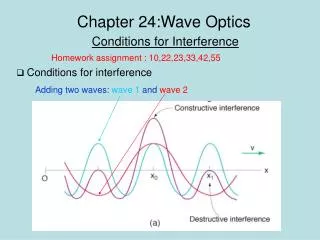
Appearance fabrication Reflectance Acquisition Fabrication Goal: Fabricating surfaces with user defined appearance • Applications: • - Architecture • Product design • Security markers visible under certain illumination conditions • Camouflage • - Photometric stereo (Johnson&Adelson 09)
BRDF (Bidirectional Reflectance Distribution Function) ? z Dot (pixel) unit on surface x
Fabricating spatially varying BRDF Reflectance Diffuse Shiny ()
Controlling reflectance via surface micro-structure Surface micro structure What surface micro-structure produces certain reflectances? Reflectance Diffuse Shiny ()
Previous work: BRDF fabrication using micro-facets theory (Weyrichet al. 09) Limitedspatial resolution Dot size ~ 3cm x 3cm Surface: oriented planner facets 3cm Surface Reflectance
Micro-facet model: limitations 3cm 0.3cm 0.03cm 0.003cm Surfacescale Wave effects at small scales => Substantial deviation from geometric optics prediction Reflectance
Previous work: BRDF design • Weyrich et al. (2009); • Fabricating microgeometry for custom surface reflectance. • Matusik et al. (2009); Printingspatially-varying reflectance • Finckh et al. (2010); Geometry construction from caustic images • Dong et al. (2010);Fabricating spatially-varying subsurface scattering. • Papas et al (2011); Goal-based caustics. • Malzbender et al. (2012); Printing reflectance functions • Lanet al. (2013); Bi-Scale Appearance Fabrication Geometric Optics
Previous work: Wave scattering • Wave models for BRDF: • He et al. 91; Nayar et al. 91; Stam 99; Cuyperset al. 12 • Holography • e.g. Yaroslavsky 2004; Benton and Bove2008 No practical surface construction Specific illumination conditions (often coherent), not general BRDF
10 Contributions: • Extra high resolution fabrication • Analyze wave effects under natural illumination • Analyze spatial-angular resolution tradeoffs • Practical surface design algorithm compatible with existing micro-fabrication technology 0.1mm 3cm
Photolithography and its limitations 11 Surface should be stepwise constant with a small number of different depth values z x Geometric optics predicts: surface is a mirror Wave optics: variety of reflectance effects Prototype: Binary depth values Restricts achievable BRDFs
Preview: reflectance = Fourier transform Surface micro-structure Reflectance Narrow Wide Diffuse Wide Narrow Shiny Anisotropic
Background: understanding light scattering 1. Coherent illumination: laser in physics lab 2. Incoherent illumination: natural world
Surface scattering – Fourier transform 2 Fourier transform See also: He et al. 91 Stam 99 z x
Inverse width relationship 2 Narrow (shiny) reflectance Wide surface features x
Inverse width relationship 2 Wide (diffuse) reflectance Narrow surface features x
Inverse width relationship 2 impulse (mirror) reflectance Flat surface x
Reflectance design with coherent illumination: • Fourier power spectrum of surface height to produce reflectance • Challenges: • Complex non-linear optimization • May not have a solution with stepwise constant heights • Inexact solutions: speckles
Speckles Noisy reflectance from an inexact surface x
Reflectance design with coherent illumination: • Fourier power spectrum of surface height to produce reflectance • Challenges: • Complex non-linear optimization • May not have a solution with stepwise constant heights • Inexact solutions: speckles • Our approach: • Bypass problems utilizing natural illumination • Pseudo random surface replaces optimization • Need to model partial coherence
Incoherent illumination: Point source=> Area source Area source = collection of independent coherent point sources x
Incoherent reflectance: blurring coherent reflectance by source angle * Coherent reflectance Angular Convolution Illumination angle x
Incoherent reflectance: blurring coherent reflectance by source angle 24 Reflectance averaged over illumination angle is smooth x
Challenge: avoiding speckles Our analysis: • Angular v.s. spatial resolution tradeoffs. • Partial coherence.
Angular resolution => Spatial coherence resolution Size of spatial unit over which illumination is coherent x
Angular resolution => Spatial coherence resolution Each coherent region emits a coherent field with speckles x
Angular resolution => Spatial coherence resolution Each coherent region emits a coherent field with speckles x
Angular resolution => Spatial coherence resolution Each coherent region emits a coherent field with speckles x
Angular resolution => Spatial coherence resolution Averaging different noisy reflectances from multiple coherent regions =>smooth reflectance. x
Angular resolution => Spatial coherence resolution Reflectance is smooth only if desired dot size Coherent size Dot size x
Angular resolution => Spatial coherence resolution Reflectance is smooth only if desired dot size Coherent size Dot size x
Angular resolution => Spatial coherence resolution Reflectance is smooth only if desired dot size Human eye resolution + typical angle of natural sources. => Smooth reflectance (see paper) Coherent size Dot size x
Recap: Coherent BRDF = Fourier power spectrum of surface height. Incoherent BRDF = Fourier power spectrum of surface height, blurredby illumination angle.
Next: Design surface height to produce desired BRDF. Coherent design:Fourier power spectrum to produce BRDF - Complex non linear optimization Incoherent design: BlurredFourier power spectrum to produce BRDF - Pseudo randomness is sufficient
Surface tiling algorithm • Randomly sample steps: • Step width ~ • Step height ~(uniform) z x z x
Surface tiling algorithm • Randomly sample steps: • Step width ~ • Step height ~(uniform) Coherent illumination => noisy reflectance x
Surface tiling algorithm • Randomly sample steps: • Step width ~ • Step height ~(uniform) Width distribution defines reflectance: = Incoherent illumination + resolution conditions: coherent size dot size => smooth reflectance x
Surface sampling Sampled surface micro-structure Reflectance Step size distribution Diffuse Glossy Shiny
BRDFs produced by our approach Isotropic Anisotropic Anti-mirror Anisotropic anti-mirrors
Fabrication results 20mm Electron microscope scanning of fabricated surface
Imaging reflectance from fabricated surface Specular spike, artifact of binary depth prototype, can be removed with more etching passes (see paper)
Imaging under white illumination at varying directions wafer camera Moving light
Vertical illumination Horizontal illumination Anisotropic BRDFs at opposite orientations Negative image
Vertical Horizontal Negative image
Narrow Isotropic Anti-mirror large incident angle: Anti-mirror kids: bright Background: dark Small incident angle: Anti-mirror kids: dark Background: bright
Limitations • Color and albedo cannot be controlled • Binary height restrictions: • Specular spike • BRDF must be symmetric • Simulation: eliminated with 4 different depths
Summary • Spatially varying BRDF at high spatial resolution (220 dpi). • Analyze wave effects under natural illumination. • Account for photolithography limitations. • Pseudo randomness replaces sophisticated surface design.
20mm Thank you! Wafer available after session