Download
1 / 23

E N D
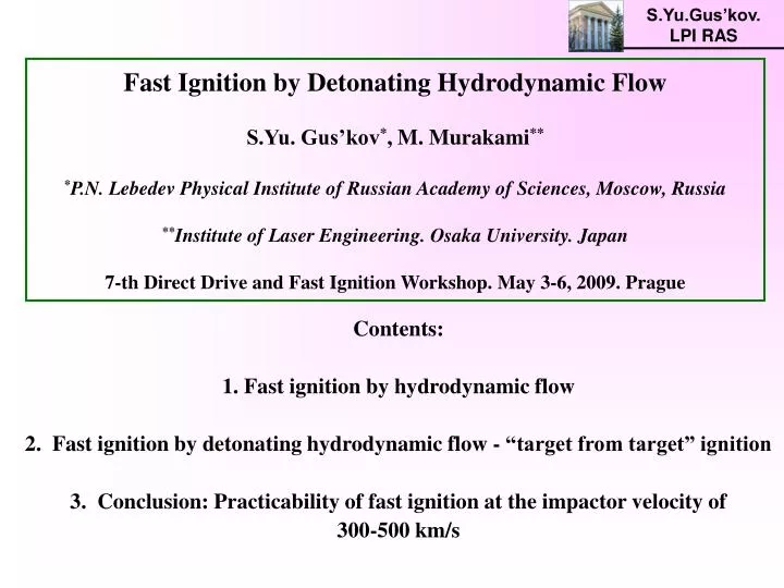
S.Yu.Gus’kov. LPI RAS Fast Ignition by Detonating Hydrodynamic FlowS.Yu. Gus’kov*, M. Murakami***P.N. Lebedev Physical Institute of Russian Academy of Sciences, Moscow, Russia**Institute of Laser Engineering. Osaka University. Japan 7-th Direct Drive and Fast Ignition Workshop. May 3-6, 2009. Prague Contents: 1. Fast ignition by hydrodynamic flow 2. Fast ignition by detonating hydrodynamic flow - “target from target” ignition 3. Conclusion: Practicability of fast ignition at the impactor velocity of 300-500 km/s
S.Yu.Gus’kov. LPI RAS Fast ignition by hydrodynamic flow
S.Yu.Gus’kov. LPI RAS Fast Ignition Drivers Compression =(300 - 500) g/cm3 R = (3 - 4) g/cm2 Ignition T=10 keV Rign = 0. 4 g/cm2 Igniting Drivers: Fast particles from laser-produced plasma • electrons(Ee ~ 0.5-1.5 MeV) • light ions (Ei ~ 10 -100 MeV/nuclon) Laser : IL > 1019 W/cm2, L< 10-20 ps. Experiments:CD-target + cone RAL (UK), ILE (Japan) Neutron yield: 105 106 Hydrodynamic pulse Iu3 , u ~1000 km/s Laser: IL 1015 W/cm2, L 1 ns Experiments:CD-target + cone ILE (Japan) Neutron yield: 105 106 Igniting Driver Energy: Eign = (10-15)/1002 kJ Eign = (10-30) kJ Beam radius: Rign=Rign / Rign 10-30mPulse duration: ign = Rign/108ign 10 ps Intensity: Iign (1018 - 1019) W/cm2
S.Yu.Gus’kov. LPI RAS Ignition of the Impactor Ignition of the Target R=3-4 g/cm2 =300-500 g/cm3 Iign t (CDTTign)3/2, ign 0.5(im /t)1/2 Iim (CDTTign)3/2 u 1.5(t /im)1/2(CDTTign)1/2 u (CDTTign)1/2 R=3-4 g/cm2 t = im u = 1500 km/s, t = 10im u > 4000 km/s, u ~1000 km/s =300-500 g/cm3 General Requirements for Impact Ignition t=300-500 g/cm3 ! Tign=10keV. I imu3 Theoretical limit of low-entropy laser-driven acceleration of a foil: 1700 km/s
S.Yu.Gus’kov. LPI RAS Profiling laser pulse Simple laser pulse Hydrodynamic fast ignition Impact along a cone ~ 1 g/cm3 V ~ 1000 km/s, M.Murakami, H. Nagatomo Nucl. Inst. & Meth. Phys. Res. A544, 67, 2005 Compression in a conical target. Detonating flow. ~ (100-200) g/cm3 V ~ (500 - 300) km/s, S. Gus’kov, M.Murakami XXX ECLIM, 2008 1000 km/s 300 km/ • ILE (Osaka University, Japan) experiments on impact ignition, EL~ (1-3) kJ, 3: • Acceleration of the foil up to record velocity: 600–700 km/s. • Impact neutron generation:(1 -2) 106 DD-neutrons/shot.
S.Yu.Gus’kov. LPI RAS Laser energy :1.3 kJ Spot size : 300 mm f Laser energy :1.9 kJ Spot size : 300 mm f 600 mm 600 mm laser laser CH plane 300 mmt Be frame Be plane (weight) Be frame CD foils 20 mmt Main fuel impactor CD foils 20 mmt Laser energy :1.9 kJ Spot size : 300 mm f laser Be frame CD foil 20 mmt ILE planar impact ignition experiments Watari T, Sakaiya T, Azachi H et al Neutron generation from impact fast ignition Proc. 5-th IFSA conference (Kobe, Japan, September 2007) 1. CD-foil - CD-target impact 3. CD-foil - CH-target impact 2. CD-foil - CD-target impact N: 106 N: 8.3105 >> N: 1.3105 1) impact nature of neutron generation and 2) neutron generation in impact-produced plasma of impactor
S.Yu.Gus’kov. LPI RAS Plastic scintillator 18 cm f × 2.5 cm 52° 178 cm Target chamber 190 cm 25° 168° Pb 10 cm 80° MANDALA 47 cm 311 cm target 1344 cm Plastic scintillator 10 cm f × 5 cm 421 detectors P M T ILE spherical impact ignition experiments Watari T, Sakaiya T, Azachi H et al. Neutron generation from impact fast ignition. Proc. 5-th IFSA conference (Kobe, Japan, September 2007 1. Nmax= 2106 2. Ti=1.59 keV 3. Nmax corresponds to coincidence of the moments of maximal compression and impact
S.Yu.Gus’kov. LPI RAS Impactor’s state before collision. Impactor’s density and velocity distributions along the central axis. L = 600 mm, t = 1.8 ns L = 1000 mm, t = 2 ns u u r r < u 600 km/s u 800 km/s > r 0.2 g / cc r 0.08 g /cc
S.Yu.Gus’kov. LPI RAS Impact-produced plasma of impactor and target Density, ion and electron temperature distributions along the central axis << L = 600 mm, t = 1.8 ns N 106 N 6.3106 L = 1000 mm, t = 2 ns Target Impactor Target Impactor Ti > Te Ti > Te r r Ti=Te Ti=Te Impactor Ti 2.2 keV, Te 1.2 keV r 0.18 g/cc Impactor Ti 6.2 keV, Te 1.8 keV r 0.12 g/cc Target Ti 80 eV, r 3.8 g/cc Target Ti 60 eV, r 3.8 g/cc
S.Yu.Gus’kov. LPI RAS Gekko/HIPER • Impactor’s density significantly less than target’s density: • imp 0.6 g/cm3 << t 4 g/cm3 • Predominant heating of impactor’s ions,Ti>>Te . Equilibrium target’s plasma Ti=Te . Impactor’s temperature significantly larger than target’s temperature: • Timp (1.5 -3) keV >> Tt (0.1 -0.2) keV • Neutron yield from impactor significantly larger than neutron yield from the target: • Nm 107 >> Nm 106 • • Confirmation of the approach: • initial ignition of impactor and subsequent propagation of detonation wave • from impactor to compressed thermonuclear fuel of ICF-target
S.Yu.Gus’kov. LPI RAS Fast ignition by detonating hydrodynamic flow
S.Yu.Gus’kov. LPI RAS Detonating impactor Development of “Cone-Guided Impactor” to “Target inside Target” Ignition by Detonating Impactor - “Target From Target” Ignition Two well-known ICF-methods: 1. Profiled Laser Pulseand 2. Initial Density Distribution Multi-layer cone target 1. Cone target with homogeneous DT-fuel and profiled laser pulse 2. Cone target with spatial distributed density Ablator Pusher Igniter Cone target Cone target Cone target ICF-target ICF-target ICF-target
S.Yu.Gus’kov. LPI RAS General requirement for ignition by detonating DT-impactor 1. Ignition of the impactor: 2. Detonation wave to DT-fuel: United requirement : Minimal ignition energy, m= t : Factor of exceeding: m t
S.Yu.Gus’kov. LPI RAS “Target from Target” Ignition by Three-Layer Cone Target
S.Yu.Gus’kov. LPI RAS • Three-layer cone target • 1. Ablator. • Light-element material: (CH)n-plastics, Be, Al and others. • Function: Acceleration of impactor laser light absorption, ablation pressure creation. • Totally evaporated at the acceleration stage. • 2. Pusher. • Heavy-element material: Cu, Pb, Au and others. • Function: Impact-driven adiabatic compression of the igniter. • 3. DT-ice Igniter. • Function: Self-burning and ignition of ICF-target DT fuel by the detonation wave
S.Yu.Gus’kov. LPI RAS Statement of the Problem. Planar Approximation. Pressure in the igniter at a burning stage: R=0.4 г/см2, T=10 keV, =100 г/см2 P~100-200 Gbar 1. Deceleration of the igniter by first shock wave, Pb0 << Pt 2. Deceleration of the pusher and adiabatic compression of the ignitor, Pb>>Pb0 3. Shock wave in ICF-Target DT-fuel; Effect of DT-fuel compressibility, Pb>Pt
S.Yu.Gus’kov. LPI RAS Compression and heating of the igniter The moment of maximal compression: deceleration of the impactor down to the velocity of shock wave in ICF-target DT-fuel Residual kinetic energy of the impactor Energy of shock wave in ICF-target DT-fuel Adiabatic compression at the initial entropy from first shock wave: 1. Residual kinetic energy of the impactor: 2. Energy of shock wave in ICF-target DT-fuel:
S.Yu.Gus’kov. LPI RAS Final state of the igniter Exact solution for m= s=t=: Compressibility factor “Uncompressible” solution Internal energy of igniter Uncompressible ICF-target fuel: Pb/Pw 1100,m 75 g/cm3; T=10 keV, at um 365 km/s; energy factor, 0.25 Au-pusher, Ms/Mm=20 Compressible ICF-target fuel: Pb/Pw 700; m 52 g/cm3; T=10 keV, at um 410 km/s; energy factor, 0.18
S.Yu.Gus’kov. LPI RAS Final igniter density and velocity of ignition Pusher and igniter mass ratio vs final igniter density 1, 2, 3, 4 - energy factor, Em /E0 = 0.3 5, 6, 7, 8 - energy factor, Em /E0 = 0.5 Tig=10 keV: initial impactor velocity vs final igniter density t=500g/cc t=300g/cc t=200g/cc - - - - uncompressible ICF-target fuel u 330 km/s Au-pusher: Mpusher/Migniter 38 DT-igniter, ()ig=0.4 g/cm2: ig 40 m Migniter 4 10-5 g Mpusher 1.5 10-4 g Initial: Eimpactor 70 kJ Final: Eigniter 40 kJ t=300 g/cm3 Eigniter/Eimpactor = 0,56 ig=100 g/cm3
S.Yu.Gus’kov. LPI RAS Conical three - layer igniting target design
S.Yu.Gus’kov. LPI RAS Igniting target. Requirements to the design 2R0 Cone opening angle 400-600 (R)ig , ig L (R)t , t Ignition of the igniter: (R)ig=0.4 g/cm2 High gain of ICF-target (R)t=3-4 g/cm2 Shell velocity: Evaporation - 50%, M0 / Mf = 2 Mass of ablator = a half of total mass, 0.3, u 0.57(I2)1/3 R0 0.153 cm, L0. 32 cm, 19.5ns Eimp=70 kJ, u = 3.3 107 cm/s, =0.3, =50o, = 0.35 m
S.Yu.Gus’kov. LPI RAS Igniting conical target design R0 0.153 cm DT-igniter: Migniter 4 10-5 g Au-pusher: Mpusher 1.5 10-4 g Be-ablator: Mablator=Mpusher Elaser= Eimpactor / Kabs Eimpactor 70 kJ = 0.3, Kabs= 0.7 Elaser 320 kJ igniter 21,3 m pusher 10.7 m ablator 115.6 m 2R00.3 cm 115.6 m 10.7 m 21,3 m L 0. 32 cm =50o
Conclusion:Practicability of hydrodynamic ignition at the velocity of 300-500 km/s • 1. Fast Ignition by Detonating Hydrodynamical Flow • Approach of “Target from Target” ignition • Conical three-layer igniting target: • Ignition at the initial velocity of hydrodynamical flow 330 km/s • and final density of detonating flow 100 g/cm3 • Laser parameters: EL= 320 kJ, L= 19.5 ns • 2. Key points: • Hydrodynamic instability • Impactor’s state before impact • EOS of heavy pusher 3. Experiments: collision of multi-layer impactor accelerated along conical or cyllindrical channels with a massive plane target.