Download
1 / 58
590 likes | 610 Views
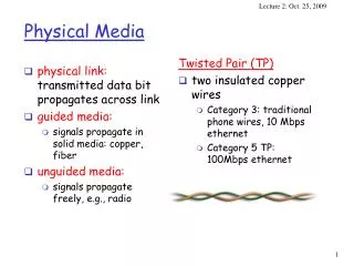
physical link: transmitted data bit propagates across link guided media: signals propagate in solid media: copper, fiber unguided media: signals propagate freely, e.g., radio. Twisted Pair (TP) two insulated copper wires Category 3: traditional phone wires, 10 Mbps ethernet

E N D
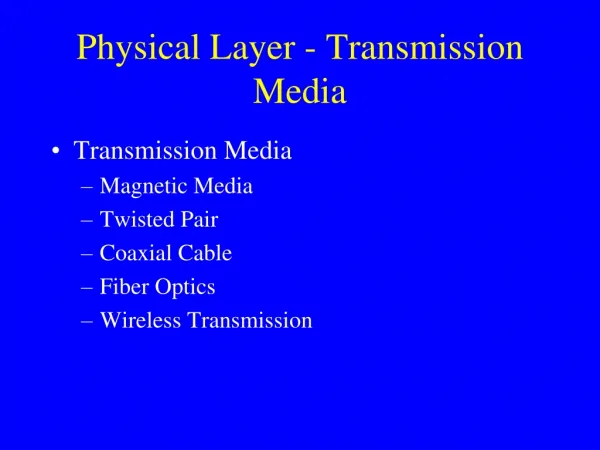
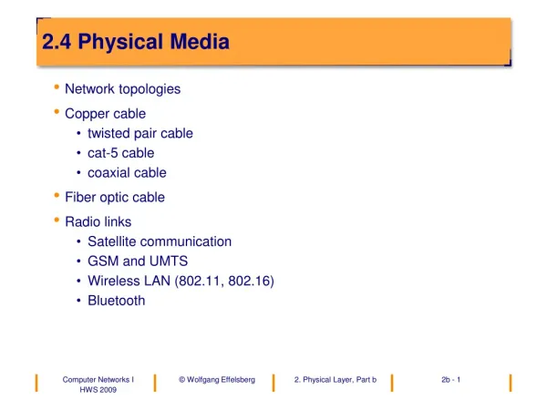
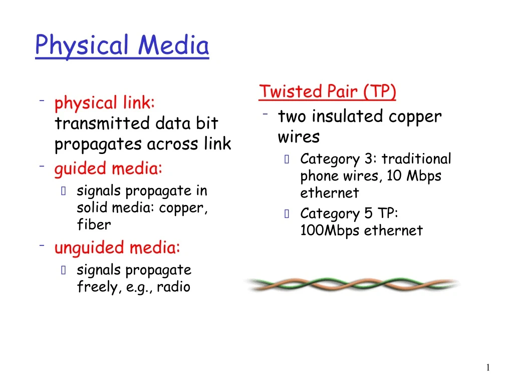
physical link: transmitted data bit propagates across link guided media: signals propagate in solid media: copper, fiber unguided media: signals propagate freely, e.g., radio Twisted Pair (TP) two insulated copper wires Category 3: traditional phone wires, 10 Mbps ethernet Category 5 TP: 100Mbps ethernet Physical Media
Coaxial cable: wire (signal carrier) within a wire (shield) baseband: single channel on cable broadband: multiple channel on cable bidirectional common use in 10Mbs Ethernet Physical Media: coax, fiber Fiber optic cable: • glass fiber carrying light pulses • high-speed operation: • 100Mbps Ethernet • high-speed point-to-point transmission (e.g., 5 Gps) • very low error rate
signal carried in electromagnetic spectrum no physical “wire” bidirectional propagation environment effects: reflection obstruction by objects interference Physical media: radio Radio link types: • microwave • e.g. up to 45 Mbps channels • LAN (e.g., 802.11b/g) • 11/54 Mbps • wide-area (e.g., cellular) • e.g. CDPD, 10’s Kbps • satellite • up to 50Mbps channel (or multiple smaller channels) • 270 Msec end-end delay • geosynchronous versus LEOS (low earth orbit)
Our goals: understand principles behind data link layer services: error detection, correction sharing a broadcast channel: multiple access link layer addressing instantiation and implementation of various link layer technologies Overview: link layer services error detection, correction multiple access protocols and LANs link layer addressing specific link layer technologies: Ethernet The Data Link Layer
M H H H H H H H H H t n l t t n l t n M M application transport network link physical M Link Layer: setting the context • two physically connected devices: • host-router, router-router, host-host • unit of data: frame network link physical data link protocol M frame phys. link adapter card
Link Layer Services • Framing, link access: • encapsulate datagram into frame, adding header, trailer • implement channel access if shared medium, • ‘physical addresses’ used in frame headers to identify source, destination • different from IP address! • Reliable delivery between two physically connected devices: • seldom used on low bit error link (fiber, some twisted pair) • wireless links: high error rates • Q: why both link-level and end-end reliability?
Link Layer Services (more) • Flow Control: • pacing between sender and receivers • Error Detection: • errors caused by signal attenuation, noise. • receiver detects presence of errors: • signals sender for retransmission or drops frame • Error Correction: • receiver identifies and corrects bit error(s) without resorting to retransmission
M H H H H H H H H H t n l t t n l t n M M application transport network link physical M Link Layer: Implementation • implemented in “adapter” • e.g., PCMCIA card, Ethernet card • typically includes: RAM, DSP chips, host bus interface, and link interface network link physical data link protocol M frame phys. link adapter card
Error Detection • EDC= Error Detection and Correction bits (redundancy) • D = Data protected by error checking, may include header fields • Error detection not 100% reliable! Q: why? • protocol may miss some errors, but rarely • larger EDC field yields better detection and correction
Two Dimensional Bit Parity: Detect and correct single bit errors 0 0 Parity Checking Single Bit Parity: Detect single bit errors Parity bit=1 iff Number of 1’s even
Sender: treat segment contents as sequence of 16-bit integers checksum: addition (1’s complement sum) of segment contents sender puts checksum value into UDP checksum field Receiver: compute checksum of received segment check if computed checksum equals checksum field value: NO - error detected YES - no error detected. But maybe errors nonetheless? Internet checksum Goal: detect “errors” (e.g., flipped bits) in transmitted segment (note: used at transport layer only)
Checksumming: Cyclic Redundancy Check • view data bits, D, as a binary number • choose r+1 bit pattern (generator), G • goal: choose r CRC bits, R, such that • <D,R> exactly divisible by G (modulo 2) • receiver knows G, divides <D,R> by G. If non-zero remainder: error detected! • can detect all burst errors less than r+1 bits • widely used in practice (ATM, HDCL)
CRC Example Want: D.2rXOR R = nG equivalently: D.2r = nG XOR R equivalently: if we divide D.2r by G, want reminder R D.2r G R = remainder[ ]
Multiple Access Links and Protocols Three types of “links”: • point-to-point (single wire, e.g. PPP, SLIP) • broadcast (shared wire or medium; e.g, Ethernet, Wavelan, etc.) • switched (e.g., switched Ethernet, ATM etc)
Multiple Access protocols • single shared communication channel • two or more simultaneous transmissions by nodes: interference • only one node can send successfully at a time • multiple access protocol: • distributed algorithm that determines how stations share channel, i.e., determine when station can transmit • communication about channel sharing must use channel itself! • what to look for in multiple access protocols: • synchronous or asynchronous • information needed about other stations • robustness (e.g., to channel errors) • performance
Multiple Access protocols • claim: humans use multiple access protocols all the time • class can "guess" multiple access protocols • multiaccess protocol 1: • multiaccess protocol 2: • multiaccess protocol 3: • multiaccess protocol 4:
MAC Protocols: a taxonomy Three broad classes: • Channel Partitioning • divide channel into smaller “pieces” (time slots, frequency) • allocate piece to node for exclusive use • Random Access • allow collisions • “recover” from collisions • “Taking turns” • tightly coordinate shared access to avoid collisions Goal: efficient, fair, simple, decentralized
MAC Protocols: Measures • Channel Rate = R bps • Efficient: • Single user:Throughput R • Fairness • N users • Min. user throughput R/N • Decentralized • Fault tolerance • Simple
Channel Partitioning MAC protocols: TDMA TDMA: time division multiple access • access to channel in "rounds" • each station gets fixed length slot (length = pkt trans time) in each round • unused slots go idle • example: 6-station LAN, 1,3,4 have pkt, slots 2,5,6 idle • TDM (Time Division Multiplexing): channel divided into N time slots, one per user; inefficient with low duty cycle users and at light load. • FDM (Frequency Division Multiplexing): frequency subdivided.
Channel Partitioning MAC protocols: FDMA FDMA: frequency division multiple access • channel spectrum divided into frequency bands • each station assigned fixed frequency band • unused transmission time in frequency bands go idle • example: 6-station LAN, 1,3,4 have pkt, frequency bands 2,5,6 idle • TDM (Time Division Multiplexing): channel divided into N time slots, one per user; inefficient with low duty cycle users and at light load. • FDM (Frequency Division Multiplexing): frequency subdivided. time frequency bands
TDMA & FDMA: Performance • Channel Rate = R bps • Single user • Throughput R/N • Fairness • Each user gets the same allocation • Depends on maximum number of users • Decentralized • Requires resource division • Simple
Channel Partitioning (CDMA) CDMA (Code Division Multiple Access) • unique “code” assigned to each user; ie, code set partitioning • used mostly in wireless broadcast channels (cellular, satellite, etc) • all users share same frequency, but each user has own “chipping” sequence (ie, code) to encode data • encoded signal = (original data) X (chipping sequence) • decoding: inner-product of encoded signal and chipping sequence • allows multiple users to “coexist” and transmit simultaneously with minimal interference (if codes are almost “orthogonal”)
CDMA - Basics • Orthonormal codes: • <ci,cj> =0 i≠j • <ci,ci> =1 • Encoding at user i: • Bit 1 send +ci • Bit 0 send -ci • Decoding (at user i): • Receive a vector ri • Compute t=<ri,ci> • If t=1 THEN bit=1 • If t=-1 THEN bit=0 • Correctness of decoding • Single user • Multiple users • Assume additive channel. • R = c1 – c2 • Output <R,c1> = <c1,c1> + <-c2,c1> = 1 + 0 = 1
Random Access protocols • When node has packet to send • transmit at full channel data rate R. • no a priori coordination among nodes • two or more transmitting nodes -> “collision”, • random access MAC protocol specifies: • how to detect collisions • how to recover from collisions (e.g., via delayed retransmissions) • Examples of random access MAC protocols: • slotted ALOHA • ALOHA • CSMA and CSMA/CD
Slotted Aloha • time is divided into equal size slots (= pkt trans. time) • node with new arriving pkt: transmit at beginning of next slot • if collision: retransmit pkt in future slots with probability p, until successful. Success (S), Collision (C), Empty (E) slots
At best: channel use for useful transmissions 37% of time! Slotted Aloha efficiency Q: what is max fraction slots successful? A: Suppose N stations have packets to send • each transmits in slot with probability p • prob. successful transmission S is: by single node: S= p (1-p)(N-1) by any of N nodes S = Prob (only one transmits) = N p (1-p)(N-1) … choosing optimum p =1/N as N -> infty ... S≈ 1/e = .37 as N -> infty
Pure (unslotted) ALOHA • unslotted Aloha: simpler, no synchronization • pkt needs transmission: • send without awaiting for beginning of slot • collision probability increases: • pkt sent at t0 collide with other pkts sent in [t0-1, t0+1]
0.4 0.3 Slotted Aloha protocol constrains effective channel throughput! 0.2 0.1 Pure Aloha 1.5 2.0 0.5 1.0 G = offered load = Np Pure Aloha (cont.) P(success by given node) = P(node transmits) . P(no other node transmits in [t0-1,t0] . P(no other node transmits in [t0,t0+1] = p . (1-p)N-1 . (1-p)N-1 P(success by any of N nodes) = N p . (1-p)N-1 . (1-p)N-1 … choosing optimum p=1/(2N-1) as N -> infty ... S≈ 1/(2e) = .18 S = throughput = “goodput” (success rate)
Aloha: Performance • Channel Rate = R bps • Single user • Throughput R ! • Fairness • Multiple users • Combined throughput only 0.37*R • Decentralized • Slotted needs slot synchronization • Simple
CSMA: Carrier Sense Multiple Access CSMA: listen before transmit: • If channel sensed idle: transmit entire pkt • If channel sensed busy, defer transmission • Persistent CSMA: retry immediately with probability p when channel becomes idle • Non-persistent CSMA: retry after random interval • human analogy: don’t interrupt others!
CSMA collisions spatial layout of nodes along ethernet collisions can occur: propagation delay means two nodes may not yet hear each other’s transmission collision: entire packet transmission time wasted note: role of distance and propagation delay in determining collision prob.
CSMA/CD (Collision Detection) CSMA/CD: carrier sensing, deferral as in CSMA • collisions detected within short time • colliding transmissions aborted, reducing channel wastage • persistent or non-persistent retransmission • collision detection: • easy in wired LANs: measure signal strengths, compare transmitted, received signals • difficult in wireless LANs: receiver shut off while transmitting • human analogy: the polite conversationalist
CDMA/CD • Channel Rate = R bps • Single user • Throughput R • Fairness • Multiple users • Depends on Detection Time • Decentralized • Completely • Simple • Needs collision detection hardware
“Taking Turns” MAC protocols channel partitioning MAC protocols: • share channel efficiently at high load • inefficient at low load: delay in channel access, 1/N bandwidth allocated even if only 1 active node! Random access MAC protocols • efficient at low load: single node can fully utilize channel • high load: collision overhead “taking turns” protocols look for best of both worlds!
Token passing: • control token passed from one node to next sequentially. • token message • concerns: • token overhead • latency • single point of failure (token) “Taking Turns” MAC protocols Polling: • master node “invites” slave nodes to transmit in turn • Request to Send, Clear to Send msgs • concerns: • polling overhead • latency • single point of failure (master)
Reservation-based protocols Distributed Polling: • time divided into slots • begins with N short reservation slots • reservation slot time equal to channel end-end propagation delay • station with message to send posts reservation • reservation seen by all stations • after reservation slots, message transmissions ordered by known priority
Summary of MAC protocols • What do you do with a shared media? • Channel Partitioning, by time, frequency or code • Time Division,Code Division, Frequency Division • Random partitioning (dynamic), • ALOHA, S-ALOHA, CSMA, CSMA/CD • carrier sensing: easy in some technologies (wire), hard in others (wireless) • CSMA/CD used in Ethernet • Taking Turns • polling from a central cite, token passing • Popular in cellular 3G/4G networks where base station is the master
LAN technologies Data link layer so far: • services, error detection/correction, multiple access Next: LAN technologies • addressing • Ethernet • hubs, bridges, switches • 802.11 • PPP • ATM
LAN Addresses 32-bit IP address: • network-layer address • used to get datagram to destination network LAN (or MAC or physical) address: • used to get datagram from one interface to another physically-connected interface (same network) • 48 bit MAC address (for most LANs) burned in the adapter ROM
LAN Addresses Each adapter on LAN has unique LAN address
LAN Address (more) • MAC address allocation administered by IEEE • manufacturer buys portion of MAC address space (to assure uniqueness) • Analogy: (a) MAC address: like Social Security Number (b) IP address: like postal address • MAC flat address => portability • can move LAN card from one LAN to another • IP hierarchical address NOT portable • depends on network to which one attaches • ARP protocol translates IP address to MAC address
Ethernet “dominant” LAN technology: • cheap $20 for 10/100/1000 Mbs! • first widely used LAN technology • Simpler, cheaper than token LANs and ATM • Kept up with speed race: 1, 10, 100, 1000 Mbps Metcalfe’s Etheret sketch
Ethernet Frame Structure Sending adapter encapsulates IP datagram (or other network layer protocol packet) in Ethernet frame Preamble: • 7 bytes with pattern 10101010 followed by one byte with pattern 10101011 • used to synchronize receiver, sender clock rates
Ethernet Frame Structure (more) • Addresses: 6 bytes, frame is received by all adapters on a LAN and dropped if address does not match • Type: indicates the higher layer protocol, mostly IP but others may be supported such as Novell IPX and AppleTalk) • CRC: checked at receiver, if error is detected, the frame is simply dropped
Ethernet: uses CSMA/CD A: sense channel, if idle then { transmit and monitor the channel; If detect another transmission then { abort and send jam signal; update # collisions; delay as required by exponential backoff algorithm; goto A } else {done with the frame; set collisions to zero} } else {wait until ongoing transmission is over and goto A}
Ethernet’s CSMA/CD (more) Jam Signal: make sure all other transmitters are aware of collision; 48 bits; Exponential Backoff: • Goal: adapt retransmission attempts to estimated current load • heavy load: random wait will be longer • first collision: choose K from {0,1}; delay is K x 512 bit transmission times • after n-th collision: choose K from {0,1,…, 2n-1} • after ten or more collisions, choose K from {0,1,2,3,4,…,1023}