Download
1 / 24
240 likes | 253 Views
This article discusses the major design features and first test results of the LCLS Prototype Undulator, including the use of titanium housing, aluminum alloy holders, and incremental shims for gap adjustment. It also explores possible design changes and improvements.

E N D
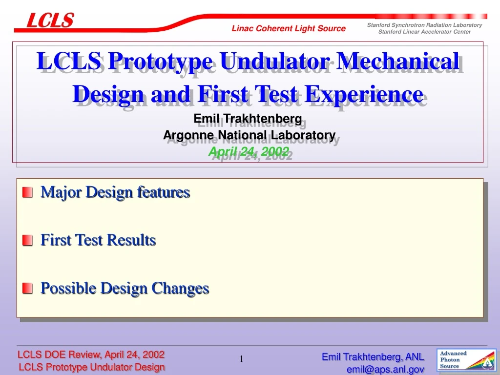
LCLS Prototype Undulator Mechanical Design and First Test ExperienceEmil Trakhtenberg Argonne National LaboratoryApril 24, 2002 • Major Design features • First Test Results • Possible Design Changes Emil Trakhtenberg, ANL
LCLS Prototype Undulator(major design features) • Titanium housing made of forged 12” bar. • Poles with so-called “wings”. • Holder of poles and magnets made of aluminum alloy to compensate the changes in the magnetization of the permanent magnets with temperature. • Only one clamp for each pole and magnet. Clamps are made of titanium. • Incremental shims or “push-pull” screw might be used for the undulator gap adjustment. Emil Trakhtenberg, ANL
Gap at the ends of the magnetic structure can be precisely tuned by piezo-translators (two on each end). • Out-bond area is completely open for the side shims to tune the field strength along the undulator. • Side shims have six bars made of low-carbon steel. Each bar can be individually adjusted and locked in place. • Five cam-shaft movers are used for alignment of the undulator as a whole. Emil Trakhtenberg, ANL
LCLS Prototype Undulator Cross Section • Window inside titanium housing is precisely machined. • Precisely machined grooves in the side racks locate pole and magnet positions in the ”Z” direction. Emil Trakhtenberg, ANL
LCLS Prototype Undulator Magnetic Structure • Shims or “push-pull” screws might be used for the gap adjustment. • Base plate of aluminum alloy was chosen to compensate the change of the field along with temperature change. Emil Trakhtenberg, ANL
LCLS Prototype Undulator Pole • Titanium “ears” are ground together finally with poles and then heat treated. • Ears are stretched out of the magnets and fit into the rack grooves. Emil Trakhtenberg, ANL
LCLS Prototype Undulator Titanium Housing Emil Trakhtenberg, ANL
Titanium Housing Deflection under Magnetic Forces Emil Trakhtenberg, ANL
LCLS Prototype Undulator on the Test Stand • Prototype undulator is installed on two steel pillars (temporarily). • Five cam-shaft movers are used for undulator alignment. Emil Trakhtenberg, ANL
LCLS Prototype Undulator Housing on the Support Stand Emil Trakhtenberg, ANL
Deflection of the LCLS Prototype Undulator Emil Trakhtenberg, ANL
Side Shim for the LCLS Prototype Undulator • There are three threaded low - carbon bars per shim. • Side shims can be installed where needed to compensate phase errors and to adjust the vertical field. Emil Trakhtenberg, ANL
End Tuning for the LCLS Prototype Undulator • The short end section of the magnet structure on both ends has slots in the base plate and in the side racks. • It allows precise tuning of the pole gap using piezo-translators. Emil Trakhtenberg, ANL
Fixture for the Magnet Structure Assembly Emil Trakhtenberg, ANL
Movers for LCLS Prototype Undulator Emil Trakhtenberg, ANL
Results of the First Undulator Motion Test-1 Emil Trakhtenberg, ANL
Results of the First Undulator Motion Test-2 Emil Trakhtenberg, ANL
Cam-Shaft Mover for LCLS Prototype Undulator Emil Trakhtenberg, ANL
LCLS Prototype Undulator Possible Design Changes • 1. Clamp each pole from both sides. • 2. Increase the rigidity of the bottom plate for the magnet • structure if still necessary. • 3. Compare the price of a round housing and an assembled one. • 4. Accommodate the wire potentiometers in the mover • design and replace the spherical double bearings with • roller bearings having an outside spherical ring. • 5. Consider the use of the precisely ground steel shims • instead of the brass ones. • 6. Shield the motors. Emil Trakhtenberg, ANL
Double Clamped Pole for the LCLS Prototype Undulator Emil Trakhtenberg, ANL
Assembled Housing for the LCLS Undulator Emil Trakhtenberg, ANL
LCLS Prototype Undulator on Magnet Measurement Stand-1 Emil Trakhtenberg, ANL
LCLS Prototype Undulator on Magnet Measurement Stand-2 Emil Trakhtenberg, ANL
Acknowledgments Vladimir Tcheskidov, Nikolai Vinokurov, Efim Gluskin, Mark Erdmann, Oleg Makarov, Thomas Powers, Isaac Vasserman, Patric Den Hartog, Elizabeth Moog, Branislav Brajuskovic, Jeffrey Collins. Emil Trakhtenberg, ANL