Download
1 / 17
170 likes | 271 Views
Neutron Imaging of Fuel Cells at NIST: Present and Future Plans. Converts neutrons to light 6 LiF/ZnS:Cu,Al,Au Note that ZnS was used by Rutherford over 100 years ago to image alpha particles backscattered from the gold nucleus

E N D
Neutron Imaging of Fuel Cells at NIST: Present and Future Plans
Converts neutrons to light 6LiF/ZnS:Cu,Al,Au Note that ZnS was used by Rutherford over 100 years ago to image alpha particles backscattered from the gold nucleus 6Li absorbs neutrons, then promptly splits apart into energetic charged particles Neutron absorption cross section for 6Li is huge (940 barns) 0.3 mm thickness absorbs 20 % of the neutrons Nuclear reaction produces energetic charged particles Charged particles come to rest in 10 – 15 microns in the ZnS ZnS:Cu,Al,Au produces green light Unfortunately light easily propagates through the screen expanding to a 200 micron blob that degrades the spatial resolution Neutron scintillator 6Li + n0 4He + 3H + 4.8 MeV Neutrons in Green light out Scintillator
Real-Time Detector Technology • Amorphous silicon • Radiation hard • High frame rate (30 fps) • 127 micron spatial resolution • Picture is of water with He bubbling through it • No optics – scintillator directly couples to the sensor to optimize light input efficiency • Data rate is 42 Megabytes per second (160 gigabytes per hour) • Most users opt for lower data rates due to the enormous pressure to download the data during and after the experiment Helium through water at 30 fps Front view Scintillator aSi sensor Readout electronics Side view Neutron beam scintillator aSi sensor
How Detectors Work • Scintillator produces after absorbing a neutron (uncertainty of 0.2 mm). • Light sensors record light distribution • Basic principle has been the same for 100 years. • Radical new method developed in a collaborative effort here at NIST will improve spatial resolution to 0.025 mm – 0.015 mm.
Microchannel Plate Detectors The general scheme is photon conversion (photocathode) or direct detection (ions/e-), 1, 2 or 3 MCPs to provide gain, and then some type of readout. For Neutron detection and imaging we have used and open face detector with MCP triple stacks and an event counting/imaging cross delay line anode Window/cathode MCPs Anode 25mm cross delay line anode detector showing anode (left), and neutron sensitive MCPs (right)
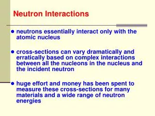
Detection of Neutrons in MCPs Absorption of Neutron Secondary(s) reaching surface Emission of photoelectron Electron gain above electronic threshold B14 MCP types use Gadolinium n + 157Gd 158Gd + γ's + X-rays + e- (29 keV - 182 keV, ~75%) σ = 70,000 b at 1 Å n + 155Gd 156Gd + γ's + X-rays + e- (39 keV - 199 keV; ~75%) σ = 17,000 b at 1 Å HB4 MCP types use Boron n + 10B 7Li (1.0 MeV) + 4He (1.8 MeV) 7% n + 10B 7Li (0.83 MeV) + 4He (1.47 MeV)+ γ (0.48 MeV) 93% σ = 2100 b at 1 Å
Ultra High Resolution • Idea proposed by NIST (Greg Downing) • Goes beyond the latest high resolution advancement • Innovative design based on a very different concept
Time-of-Flight (ToF) Coincidence Encoder Neutron Beam Neutron Converter Encoder
t2 t1 The reaction gives a unique coordinate solution • Known: • Mass of each particle • Initial energy of each particle • Stopping power of converter • Stopping rate for each particle is different • Measure: • The unique time of flight (ToF) for each particle pair • Two PSD encoders establish the x-y coordinates for each pair • Impose conditions: • Min./Max. delta time window for the coincidence pair • Line segment must pass through detector volume • Particle pair must yield a unique depth • A Jacobian Transformation defines unique angular emission & confirms measured angle • Calculate: • TOF Residual energy for each particle pair unique depth (x) of each reaction • Position sensitive encoder establishes a unique (y,z) position for the reaction • Variation in time/energy/stopping power/x-y position give spatial uncertainty • List mode output
Wet Dry Additional Water Content Due to Current 100 mA/cm2 60°C, 100% RH, 2 stoic @ 1.5A/cm2 650 mA/cm2 DVH2O (mL) 1250 mA/cm2 fractional distance from inlet The highest water content is not always observed at the greatest current density. There is a competition between water generation and local heating. Collaborator: Sandia National Lab
Logical test applied at the exit of each volume: If ( > ) Then VolumeN = Saturated 1 1 2 2 3 3 1 2 3 6 6 5 5 4 4 6 5 4 7 7 8 8 9 9 7 8 9 12 12 11 11 10 10 12 11 10 13 13 14 14 15 15 13 14 15 18 18 17 17 16 16 18 17 16 19 19 20 20 21 21 19 20 21 24 24 23 23 22 22 24 23 22 25 25 26 26 27 27 25 26 27 30 30 29 29 28 28 30 29 28 31 31 32 32 33 33 31 32 33 Down-channel condensation model at Bulk Cell Temperature of 60°C VolumeN 0.5 A/cm2 cell 2 – predicted cell 2 – actual 1.0 A/cm2 cell 4 – predicted cell 5 – actual 1.5 A/cm2 cell 7 – predicted cell 8 – actual Collaborator: Sandia National Lab
MEA Hydration Characterization Water after 20 min purge with Dry Nitrogen Water after 40 min purge with Dry Nitrogen Initial Water Content • Assume the water content underneath the gaskets is due solely to MEA water • Can evaluate membrane hydration without interference from GDL or channel water • Red is average active area water content, Blue is average water content under gasket • Future studies planned to assess the method • Accepted in Journal of Power Sources Collaborator: Rensselaer Polytechnic Institute, Plug Power
High Flow Rate DP Low Flow Rate Neutron Detector/ Imaging Device Neutron beam Gas Out Gas In GDL sample Sample holder DP Time Water reservoir (a) (b) Capillary properties of GDLs and Catalyst layers via Neutron Radiography Capillary Pressure of GDLs Sketch of Capillary Pressure Experiment Capillary Pressure of Thickened Catalysts Gas Permeability versus saturation In collaboration with T.V. Nguyen, et al
Modeling a single serpentine Fluent Model Neutron Imaging Data In collaboration with X. Li and J. Park, U. Waterloo
First Data with 0.025 mm resolution • Membrane swelling complicates data analysis • Use 0.02 A cm-2 as the reference state to analyze change in water content • Improved mounting scheme will eliminate the issue
Future Plans, Freeze Chamber • Manufacturer, Thermal Product Solutions • -40 C to +50 C, +/- 1 C stabilization • 1000 kW cooling at -40 C • 32” W, 24” H, 18” D sample volume • Hydrogen safety features • Explosion proof components • Hydrogen sensor in return, will tie into Facility E-stop • Nitrogen gas as cooling/heating fluid • Remote Control Panel • Air handling unit to reside permanently inside BT2 • Install hopefully during Feb. shutdown, definite operation by April