Download
1 / 27
270 likes | 427 Views
LLRF upgrades and new Comb-2 project. Mike Browne D. Brown, R. Chestnut, J Dusatko, M. Laznovsky, W. Ross, W. Roster, C Yee. Outline. System Performance Summary System Issues LLRF Module Status IOC CLOCK IQA AIM RFP COMB Other Status COMB-2 Project. LLRF. LLRF. LLRF?.

E N D
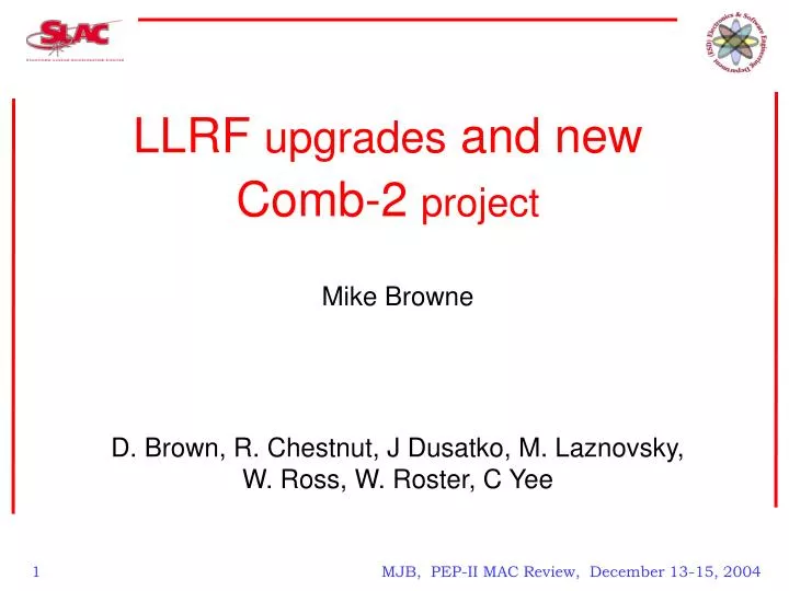
LLRF upgrades and new Comb-2 project Mike Browne D. Brown, R. Chestnut, J Dusatko, M. Laznovsky, W. Ross, W. Roster, C Yee MJB, PEP-II MAC Review, December 13-15, 2004
Outline • System Performance Summary • System Issues • LLRF Module Status • IOC • CLOCK • IQA • AIM • RFP • COMB • Other Status • COMB-2 Project MJB, PEP-II MAC Review, December 13-15, 2004
LLRF LLRF LLRF? RF Fault Summary for PEP-II RUN 4 RF fault analysis over 313 days (09/22/2003 - 07/30/2004) 1190 faultsAverage of 3.8 aborts per day (2.9 without non-RF events) Compiled by Dmitry Teytelman & Dan Van Winkle MJB, PEP-II MAC Review, December 13-15, 2004
LLRF System Issues • The Following Issues Surfaced During RUN 4: • Station Phase Drifts - Lead to 47 Aborts • COMB Module Overflow Faults - Lead to 34 Aborts • Various VXI Module Failures (Clock, COMB, RFP, IQA) • RUN 4 Also Saw Some System Improvements: • Upgraded to new RFP Modules in all stations • 4 with new fixes • Upgraded to new IOCs in all stations • Upgraded to new IQAs for all cavity IQA locations • Used 8 channel scanning mode to obtain Fault data for all channels. • Tested new Arc Interlock Module new HVPS monitor channels • HVPS DC Voltage and current monitors • HVPS Ripple and fast Current Transformer Monitor • The Current Transformer will be helpful in analyzing station performance and trips • tested on HR8-1 MJB, PEP-II MAC Review, December 13-15, 2004
LLRF System Issues • Phase Drifts • Isolated to 3 leading sources: • RFP Module Circuit Sensitivity • Fixes Described later • LLRF System Rack Temperature Instability • Clock Module RF Amplifier Failures • COMB Overflow Faults • Developed Initial SW fix (“Band-Aid”) • Developed HW FIX to Resolve Problem • VXI Module Failures • Component Aging • Connector Wear & Tear • Random Failures on Some Modules • Swap & Repair as we found them MJB, PEP-II MAC Review, December 13-15, 2004
LLRF Module Status- IOC • Old NI 68030/40MHz IOCs were replaced with KSC PPC 350MHz Units • The old IOCs were seriously performance limited • (80% – 90% loading) • A MAJOR development effort was undertaken to adapt the new IOC for LLRF: This work was performed by John Dusatko • Modified 63 LLRF VXI Modules last summer to fix design issue • Reverse-Engineered & Modified KSC IOCs to fix design bugs • Developed Special SW / Fixes to KSC SW as well • Had to adjust some LLRF system SW task timing for increased speed RESULT: Tremendous Performance Increase < 8% loading (typ) • As of 7-13-2004 ALL LLRF Station Have Been Upgraded • Have 6 Spares / 2 destined for New LLRF Stations / Looking into getting more • Motorola Has Informed us that the MVME2400 will go away in 2005!(We have a recommended substitute) MJB, PEP-II MAC Review, December 13-15, 2004
LLRF Module Status- IOC cont. Station with OLD IOC: Station with NEW IOC: MJB, PEP-II MAC Review, December 13-15, 2004
LLRF Module Status - CLOCK • Current System contains a mix of (8) old (R1) and (3) new (R2) modules • Saw Several R1 Clock Failures This RUN • Mainly Due to RF Amplifier Death (selected different device for repairs) • Some Bad RF Connectors as well (Wear & Tear) • Bad Modules Were Swapped and repaired • Amplifier Failures Prompted a system-wide measurement of Clock RF output power levels. • We have replaced all old style RF Amps on all remaining Clock modules the during the downtime • Originally only built (5) New Modules for Added Stations / Building qty = 10 more R2 Clock Modules • We suspect that some old CLKs are contributing to Phase Drift Problem • Considering replacing ALL clocks with R2 versions at some point MJB, PEP-II MAC Review, December 13-15, 2004
LLRF Module Status - IQA • New Version (R3) of IQA was designed, built & installed (Built 23 / 20 Installed) The new version has an eight channel mode, for displaying fault histories of all channels. • System now contains a mixture of old and new modules • IQAs have been performing fairly well / no major problems • We have seen several older modules with both intermittent and solid connector failures. • Discussed creating a Design Proposal for new version (more robust / enhanced features / simplified design/very few connectors) • This is a long-term item: • Not Terribly Critical at this point MJB, PEP-II MAC Review, December 13-15, 2004
LLRF Module Status - AIM • More version 2 AIMs were built & installed in all stations during the summer down time. • Last run the system has mix of (3) old (R1) & (8) new (R2) modules • All stations were their HVPS channels wired to the new AIMs. MJB, PEP-II MAC Review, December 13-15, 2004
LLRF Module Status - RFP • New RFPs were installed in all 11 LLRF stations during last run. • Phase Stability Improvements: • Discovered that several RFP circuits were contributing to phase drift and operating point errors • Reduce circuit impedance at coefficient input of the Gilbert-cell multipliers -reduced offset 5 times • Made the comb multiplier signal capacitive-coupled. • Changing amplifier operating point to reduce D.C. drift by a factor of 2 Replaced old difference amplifier in multiplier circuits with lower drift amplifiers (>20x improvement) • Found bias current offset problems causing large “Tune” mode offset. • Developed corrections and tested Successful: RFPs are now more stable, far less sensitive to temperature variation, smaller operating errors • (4) RFPs were tested in PEP-II at the end of Run 4. • All other RFPs have been modified during the summer downtime • Other Work • Mike Laznowsky rewrote the Calibration SW to accommodate new functions and fix standing problems. His new code is much cleaner, compact and runs 10 times faster than the old version. 2 minutes verses 20. MJB, PEP-II MAC Review, December 13-15, 2004
LLRF Module Status - COMB • We saw many COMB overflow faults this run • (this has been a known design flaw) • Overflow typically causes spurs at ½ 136KHz rate that perturb the beam • Created Two Fixes • SW “Band-Aid”: alert operators to manually clear fault • HW Fix: Add-on daughterboard -- Corrects Design Flaw / Overflow is now handled correctly (D. Teytleman & D. Van Winkle) • A prototype of fix #2 was created and tested: good results -overflows stopped • A Production version of this Daughterboard has been created, fabbed and assembled (qty = 30) • All COMBs were upgraded with these daughter boards during the downtime. • Meanwhile a new COMB-2 Module is being designed (W. Ross) • More on this later MJB, PEP-II MAC Review, December 13-15, 2004
Other Status - LLRF System Cooling • In Investigating LLRF Phase Drift, we decided to look at the LLRF rack cooling system • Discovered several issues: • ELMA VXI Crate airflow design is poor • A/C Units not operating efficiently / temperature not well-regulated / most compressor control relays were welded ON • Overall thermal design is sub-optimal • Devised Several Fixes • Insulate The LLRF Rack • Improve airflow steering in rack • Enhance the A/C unit with PID Loop / Heater / Blower Control • Modify the VXI crate for better airflow • Have Tried first three fixes on LR4-5 and items 2 and 3 on LR4-3 • Results show that the temperature is now much more stable • See figure • We plan to upgrade all LLRF stations at some point but, we did not do this during the summer down time due to limited resources MJB, PEP-II MAC Review, December 13-15, 2004
Other Status - LLRF System Cooling Ambient & Crate Temperature For Station with Enhanced Cooling System MJB, PEP-II MAC Review, December 13-15, 2004
Other Status – Phase Reference System • RF Phase Reference Distribution System is being improved to reduce phase drift. • This work is being done by Bill Roster • We have and fabricated new Tx boards for the phase controllers and Rx boards for the distribution units. • These boards have been installed in all controllers and distribution units in the system. • We are adding new RF detector boards with higher gain to improve the overall gain stability in the control path. These will be installed this week. • We will monitor the system over the next few weeks to see whether if the system is more stable. MJB, PEP-II MAC Review, December 13-15, 2004
COMB-2 PROJECT W.Ross , M. Browne PRINCIPAL ENGINEER AND TASK LEADER C Yee, M. Laznovsky Major Contributors MJB, PEP-II MAC Review, December 13-15, 2004
COMB-2 PROJECT OUTLINE • FEATURES • BLOCK DIAGRAM • DSP’ FPGA FIRMWARE • ‘DSP’ FPGA UTILIZATION • PROJECT TASKS • PC PARTS PLACEMENT • PC BOARD LAYER STACK • PROJECT TASK LIST • PRODJECT SCHEDULE • PROJECT RESOURCE LIST MJB, PEP-II MAC Review, December 13-15, 2004
COMB-2 FEATURES • Combined I Channel and Q Channel Processing in a Single Module • Fixes Over-flow and VXI interface bugs present in old Combs • Flexible ‘DSP’ FPGA design: • The filtering algorithms can be changed in the future by re-programming the In-Circuit-Programmable Initialization ROMs. (J-tag port) • Initial DSP Functionality: • Initially, Comb 2 Module will be firmware programmed to perform the full 2-dimensional Comb Filter and Equalization processes, implementing the additional I to Q and Q to I filters which were not available in the earlier version Comb Modules. • Inter- module Analog Connection: • I/Q signals between the RFP module and the Comb Module will be differential analog via the VXI Backplane local bus lines for compatibility with current RFP • Serial Data Link for a Possible Future Digital RFP Module • Via an Infiniband connector on the front panel. The total serial bit-rate using 8/10-bit coding is 1.4 GBits/Sec in each direction. This link will be tested but not implemented in the initial design. MJB, PEP-II MAC Review, December 13-15, 2004
COMB-2 BLOCK DIAGRAM MJB, PEP-II MAC Review, December 13-15, 2004
COMB-2 DSP’ FPGA FIRMWARE Design implemented in the ‘DSP’ FPGA Firmware: MJB, PEP-II MAC Review, December 13-15, 2004
COMB-2 ‘DSP’ FPGA UTILIZATION ‘DSP’ FPGA The initial design implementation uses approximately 30% of the resources of the XC2VP30. We are using the 896 pin BGA version of this part and the “– 7” the fastest speed grade. This should allow considerable flexibility for any future upgrade. MJB, PEP-II MAC Review, December 13-15, 2004
COMB-2 PC PARTS PLACEMENT MJB, PEP-II MAC Review, December 13-15, 2004
COMB-2 PC BOARD LAYER STACK • 16 LAYER BOARD • 10 TRACE LAYERS • 6 POWER/GND • BURRIED CAPACITANCE • LAYERS 2/3, 8/9, 14/15 BC-24 MATERIAL MJB, PEP-II MAC Review, December 13-15, 2004
COMB-2 PROJECT TASK LIST • FUNCTIONAL SPECIFICATION DEVELOPMENT AND APPROVAL • INITIAL ALGORITHM / ARCHITECTURE DESIGN FOR DSP PROCESSES • DEVELOPE INITIAL VHDL FIRMWARE FOR “DSP” FPGA (to determine required DSP FPGA size) 3.1 VHDL CODE WRITING - “DSP” FPGA” 3.2 SIMULATION OF VHDL SUB MODULES AND TOP LEVEL MODULE – EPD (to debug VHDL code) 3.3: VIRTEX2-PRO PART IMPLEMENTATION - XILINX ALLIANCE (to determine part size for ‘DSP’ FPGA) 3.4: MATLAB SIMULATION OF DSP SUB-MODULES (to assure transfer functions, sufficient dynamic range, decimal point alignment, and overflow management) 3.5 MODIFY VHDL CODE AS REQUIRED - FINALIZE VHDL CODE 4. DEVELOPE VHDL FIRMWARE FOR “VXI -INTERFACE” FPGA 4.1 VHDL CODE WRITING - “VXI -INTERFACE” 4.2 FUNC. SIMULATE - IMPLEMENT (FIT) FPGA - TIME SIMULATE 5. EPICS SOFTWARE DRIVER AND DIAGNOSTICS PANEL DEVELOPMENT XXCOMPLETE XX IN PROCESS XXNOT STARTED MJB, PEP-II MAC Review, December 13-15, 2004
COMB-2 PROJECT TASK LIST CONT. 6. DESIGN BOARD LEVEL SCHEMATICS • 6.1: SCHEMATICS DESIGN - EPD • 6.2: SIMULATE AT SCHEMATIC LEVEL - EPD 7. WRITE MODULE DIAGNOSTICS SOFTWARE 8. PARTS ACQUISITION (all parts for prototypes, some parts for full production) 9. PC BOARD LAYOUT – PROTOTYPES 10. PC BOARD FABRICATION - PROTOTYPES 11. FRONT PANEL LAYOUT AND FABRICATE 12. PARTS KITTING AND PC BOARD ASSEMBLY - PROTOTYPES 13. HARDWARE PROGRAMMING, TESTING, TEST PLAN DOC - PROTOTYPES 14. SOFTWARE DRIVER TESTING AND INTEGRATION INTO LLRF SYSTEM 15. MODIFY DESIGN AND PC BOARD LAYOUT AS REQUIRED ( for production) 16. ADDITIONAL PARTS ACQUISITION (for production) 17. PC BOARD FAB (for production) 18. PARTS KITTING AND PC BOARD ASSEMBLY (for production) 19. PRODUCTION HARDWARE/SOFTWARE TESTING (production modules) XXCOMPLETE XX IN PROCESS XXNOT STARTED MJB, PEP-II MAC Review, December 13-15, 2004
COMB-2 PRODJECT SCHEDULE W. Ross 11/15/04 MJB, PEP-II MAC Review, December 13-15, 2004
COMB-2 PROJECT RESOURCE LIST SLAC, ESD, LLRF GROUP MJB, PEP-II MAC Review, December 13-15, 2004