Download
1 / 61
620 likes | 832 Views
ORiNOCO Outdoor Router Installation. Module contents. Network Topologies HW Setup COR/ROR System configuration Outdoor Client Installation / configuration Antenna installation Troubleshooting. ROR. ROR. ROR. ROR. ROR. ROR. 2.0 Km. 15.0 Km. 100 m.

E N D
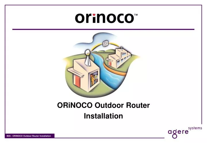
ORiNOCO Outdoor Router Installation
Module contents • Network Topologies • HW Setup • COR/ROR System configuration • Outdoor Client Installation / configuration • Antenna installation • Troubleshooting
ROR ROR ROR ROR ROR ROR 2.0 Km 15.0 Km 100 m ORiNOCO Outdoor RouterTopologies - basic setups Point to Point - Yagi Point to Point - Parabolic Point to Point - Mixed Outdoor Router and Access Point
ROR ROR ROR ROR COR ROR ROR ROR ROR 100 m 100 m ORiNOCO Outdoor RouterTopologies - advanced setups Point to Point Multiple buildings Repeater 2 Channels Point to Point with Access Point Nodes 2 or 3 Channels ? Point to Point RF, Pt to MultiPoint Logic 1 ch. for Links 1 ch. for Access Point
COR ROR ROR ROR ROR ROR ROR ROR ROR ROR ORiNOCO Outdoor RouterTopologies - advanced setups Maximum Three Point to Point links using three Frequencies Using Splitters to create RF Point to Point links with single Channel. Calculate RF for 1 to 4 splitter, -6dB per side less Insertion loss.
ROR ROR ROR COR ORC 1.0 Km ORiNOCO Outdoor RouterTopologies - basic network Basic Point to Multipoint, Distance increase using Sectorial Antennas
ROR ROR ROR COR ROR ORC 1.0 Km ORiNOCO Outdoor RouterTopologies - adding a single remote location Point to Multipoint with Uplink
COR/ROR ROR ROR ROR ROR COR ROR ROR ORC ORC 1.0 Km ORiNOCO Outdoor RouterTopologies - concatenating a second cell Two Multipoint ‘cells’ linked with dedicated ROR to COR Point to Point link
COR/ROR COR/ROR ROR ROR ROR ROR ROR ROR ORC ORC 1.0 Km ORiNOCO Outdoor RouterTopologies - concatenating a second cell Multipoint ‘cells” linked with ROR to shared COR - expandable to many cells
COR Yagi Antenna, 35 degree, 3.5km Parabolic Antenna, narrow 15 degrees, long distance ( 8km ) 120 Degree Sectoral, covers 3 Km 120 Degree Sectoral, covers 3 Km ORiNOCO Outdoor RouterTopologies - fine tuning the antenna pattern
ORiNOCO Outdoor RouterSystem Components • ORiNOCO COR-1100 • AP-1000 (WP-IIE) Hardware • Omni directional antenna • Supports up to 16 “ROR-1000” units or up to 32 “ORCs” • ORiNOCO ROR-1000 • AP-1000 (WP-IIE) Hardware • Directional antenna • Connects to “COR-1100” (point-to-multipoint), or to another “ROR-1000” (point-to-point). • Is Master or Slave in ROR-ROR config. • ORiNOCO ORC • Windows95/98/2000/NT4 PC • Outdoor Router Client software upgrade kit • ORiNOCO Turbo 11 Mb PC Cards
ORiNOCO Outdoor RouterElements - AP-1000 (WP-IIE) HW • Standard AP-1000 (WP-IIE) Hardware • 486-DX2 133 MHz processor • 4 MB of memory • 256 KB Flash ROM • On board Ethernet LAN • 10Base-T, 100Base-T (UTP) • Two PCMCIA slots for ORiNOCO PC Cards • Separate 5V Power Supply • 4 LEDs to indicate status
ORiNOCO Outdoor RouterConnecting to the antenna assembly To connect the ORiNOCO Turbo 11 Mb PC Card to the external antenna: A. “pigtail cable” assembly 1. Proprietary connector 2. Standard-N Female connector B. Surge/lightning protector Standard-N female connector (both sides) C. Low-loss antenna cable Standard-N male connector (both sides) D. Outdoor antenna Standard-N female connector (both sides)
ORiNOCO Outdoor RouterPhysical indicators LEDs • start-up diagnostics of unit takes 40 sec. • LEDs will show Amber, Red or Green • Run time, the LEDs show (from left to right): • Power (Green) Power enabled • Ethernet (Flicker Green) Ethernet LAN activity • Wireless A (Flicker Green) Wireless LAN activity on slot A • Wireless B (Flicker Green) Wireless LAN activity on slot B
C(0103) A(0101) B(0102) A(0101) B(0102) C(0103) ORiNOCO Outdoor RouterConfiguration - setup Configuration and management of the AP-1000 (WP-IIE) devices can be done by running ORiNOCO OR Manager on a station connected to the wired backbone, or on a mobile station.
ORiNOCO Outdoor RouterORiNOCO OR Manager - Startup screen • Install ORiNOCO OR Manager on Windows 95, 98 or NT4 machine(running the setup routine) • Will create a Program menu item for easy activation • Will be used for • Configuration • Monitoring bridges • Analyzing links • Upgrading bridge Software
ORiNOCO Outdoor RouterORiNOCO OR Manager - File menu • “Open Config File…” loads a file from disk • “Open Remote Config…” accesses a Outdoor Router to obtain its configuration data • “Save Config” returns the file from memory to the place where it came from • “Save Config As..” makes a disk copy of the config file • “Import Config File…” inserts a configuration set in a loaded file in memory • “Upload Software...” loads a new bin file in the AP-1000 (WP-IIE)
ORiNOCO Outdoor RouterORiNOCO OR Manager - Setup Menu • Becomes available when a config file has been obtained
ORiNOCO Outdoor RouterORiNOCO OR Manager - Monitor Menu • Monitoring allows the user to assess statistics maintained by a specifically identified Outdoor Router device • Requires selection of a device (or by loading its config file)
ORiNOCO Outdoor RouterORiNOCO OR Manager - Analyze Menu • Allows execution of a wireless link test between an Outdoor Router and any wirelessly connected device • Requires selection of a device (or by loading its config file)
ORiNOCO Outdoor RouterORiNOCO OR Manager - to access a device • ORiNOCO OR Manager station and device to be accessed need to be in the same subnet • Check TCP/IP settings of Notebook with ORiNOCO PC Card or Ethernet Adapter • Default IP address of AP-1000 (WP-IIE) is 153.69.254.254 • Option to change IP address of ORiNOCO Outdoor Router on first scan
ORiNOCO Outdoor RouterORiNOCO OR Manager - General Setup • Do not check “Enable IP Routing” if only bridging is required • Not checking “Enable IP Routing” leaves the “General Setup Menu” as is: • “IP Setup” is available
ORiNOCO Outdoor RouterORiNOCO OR Manager - IP setup • IP address of Outdoor Router can be assigned manually or by DHCP
ORiNOCO Outdoor RouterORiNOCO OR Manager - General Setup • Check “Enable IP Routing” when the device is used as Router • Checking “Enable IP Routing” changes the “General Setup Menu”: • “IP Setup” is becomes IP Router Setup
ORiNOCO Outdoor RouterORiNOCO OR Manager - Router setup • IP address of the Outdoor Router can be entered as “Preferred IP Address”
ORiNOCO Outdoor RouterORiNOCO OR Manager - Interface setup • To identify which interfaces are active • To set the parameters for the Network Interface devices (Ethernet and ORiNOCO PC Card) • If Firewall is implemented, check the “Remote” checkbox for traffic from beyond the firewall • Transmit rate limit can be identified for each I/F (throttling).
ORiNOCO Outdoor RouterORiNOCO OR Manager - Station setup • Station selection is made after selecting on of the wireless interfaces • Depending on license keys different selections are possible: • Point-to-multipoint license: • Central Outdoor Router • Remote Outdoor Router (Slave) • Point-to-point license • Remote Outdoor Router (Master) • Remote Outdoor Router (Slave) • Protocol filtering options only present for COR
ORiNOCO Outdoor RouterORiNOCO OR Manager - Station setup • When using ORINOC PC Card in Access Point mode, the window allows entry of the “Network Name” • Clicking “Advanced” shows the regular settings for Access Point mode of operation
ORiNOCO Outdoor RouterORiNOCO OR Manager - Wireless setup • After selecting a wireless interface changes can be made to: • Frequency (channel); number of channels available depend on country • Link speed, High to Low (11 Mbps to 1 Mbps) • Encryption (depending on type of card can be 64 WEP or 128 RC4) • When multiple CORs are deployed in same area, Network IDs are needed to logically separate them (0-15) • Clicking Advanced in “OR” Mode differs from AP Mode
ORiNOCO Outdoor RouterORiNOCO OR Manager - Bridge setup • Bridge Setup menu is available if Bridging is selected in “General Setup” • To increase performance protocol filtering can be applied. • If needed Address Pairs can be added to block traffic between two MAC addresses. • Storm thresholds can be set to indicate the level above which traffic will be filtered
ORiNOCO Outdoor RouterORiNOCO OR Manager - Protocol filtering • Clicking “Edit” on Bridge Setup present a list of protocols that can be filtered • If protocols are not in the list they can be added by pressing “custom” • When selected the protocol can be identified as “denied” or “bridged”
ORiNOCO Outdoor RouterORiNOCO OR Manager - Routing table setup • Routing tables need to be set up to transport packets between sub-nets. • Subnets are specified as either “directly” connected to the OR or “indirect” • For each active interface an “direct entry” is made specifying the base IP address of the directly connected sub-net • The “Interface/Cost” portion of the entry indicates the interface number
ORiNOCO Outdoor RouterORiNOCO OR Manager - Routing table setup • Sub-nets not directly connected are entered as “indirect entry” • Indirect entries are routed via a target router that is on one of the direct connected sub-nets • The “Interface/Cost” portion of the indirect entry entry indicates the path cost metric
195.1.32.1 195.1.40.2 B 130.2.247.1 195.1.32.2 195.1.40.1 195.1.30.1 130.2.246.1 A 130.1.210.1 195.1.30.4 130.2.249.14 195.1.30.2 195.1.30.3 195.1.30.6 130.2.233.12 ORiNOCO Outdoor RouterORiNOCO OR Manager - Routing table setup
ORiNOCO Outdoor RouterORiNOCO OR Manager - Routing using RIP1 • Set interfaces on which RIP protocol is to be sent and received • Sending RIP will impact throughput • DHCP Forwarding across router - set on port with DHCP clients, set IP of DHCP server • access RIP setup using “more” key on IP router screen • Using RIP set up only Direct Routes, send Routes from ROR, listen on COR
ORiNOCO Outdoor RouterORiNOCO OR Manager - Routing table ROR Table with default Route set to COR interface Routes learned from ROR via RIP
ORiNOCO Outdoor RouterORiNOCO OR Manager - SNMP Setup • Allows setting information needed for SNMP operations • Read and Read/Write passwords to control access to a remote config file • Trap Host IP address - address of the System capable of accepting the traps (e.g. HP Openview)
ORiNOCO Outdoor RouterORiNOCO OR Manager - Monitoring • Remote Statistics (tallies kept for the active interfaces)
ORiNOCO Outdoor RouterORiNOCO OR Manager - Monitoring • Remote Statistics (tallies kept for the active interfaces) as defined by the RFC in MIB-II
ORiNOCO Outdoor RouterORiNOCO OR Manager - Monitoring • Showing all connected remote stations • Identifies per link the quality of the link • “Signal”, “Noise” and “SNR” show the current perceived conditions • “Excellent”, “Good” and “Low” show number of transmission tallied with those qualifications
ORiNOCO Outdoor RouterORiNOCO OR Manager - Monitoring • Advanced monitoring functions that tally statistics: • SNMP Monitor • IP Monitor • IP-TCP/UDP Monitor • ICMP Monitor • System Information (to indicate release version of the SW) • Dynamically-built tables
ORiNOCO Outdoor RouterORiNOCO OR Manager - Remote link testing • Wirelessly connected stations show up in the “explore window”. • Link test can be executed from any AP-1000 (WP-IIE) that can be accessed to any remote station that can be explored from that AP-1000 (WP-IIE) • Link test shows RF characteristics in animated fashion
ORiNOCO Outdoor RouterSoftware - Outdoor Router Client Software includes: • Outdoor Router driver to install on desktop/laptop PC, operating with ORNICO PC Card • Downloadable from web-site • Protected by license • Customer (I.e. ISP) buys a license (gets a number), to use software • Requires specification of bandwidth to be used (64, 128, 256, 384, 512, 1024 Kbps) • Using the number a license key (and MAC address of PC Card) can be obtained
ORiNOCO Outdoor RouterOutdoor Router Client Installation • Installing the Outdoor Router Client (ORC) requires: • Desktop or laptop computer with running Windows (95/98/NT4/2000) • ORiNOCO NIC (PC Card, PCI Card, ISA Card) • ORC Software License • ORC Software (downloaded from web site) • Antenna system • Inserting the NIC in the platform computer triggers Windows hardware detect process • Follow the instructions on screen and where requested insert the disk with the ORC software (or direct Windows to the location where the ORC software is stored)
ORiNOCO Outdoor RouterOutdoor Router Client Installation When Windows has located the ORC driver the following screen is shown: • License Number: the number obtained via the license key process • Pass Phrase: The key used during the registration process should match the Pass Phrase entered on the COR (System Access Setup) • Data Rate: Value indicated by the license agreement • Frequency Channel: match the choice on the COR • Network ID: match the choice on the COR • Transmit Rate: same as choice on the COR
ORiNOCO Outdoor RouterAntenna installation - Guidelines • Planning • Calculate distance • Determine required antenna • Determine antenna position • Installing • Bridge systems (ORiNOCO Outdoor Router) • Antenna mounting • Aligning • Maintenance • Monitoring / trouble shooting
ORiNOCO Outdoor RouterAntenna alignment (directional antennas) • If stations see each other: • Line up based on sight • Assure both horizontal and vertical alignment • Align both antenna’s • If stations cannot see each other: • Use GPS and map to establish the vectors • Use compass to align the antennas according to the vectors • Move the antenna’s until link is good or acceptable • Align both antenna’s
ORiNOCO Outdoor RouterAntenna alignment (directional antennas) • Run SW tools to fine tune the alignment • ORiNOCO OR Manager’s remote point to point • Move the antenna’s until link is good or acceptable
ORiNOCO Outdoor RouterAntenna installation -Tools to use • To select proper antenna, use • ORiNOCO Outdoor Router range Calculation spreadsheet • To line up directional antenna’s use: • GPS to identify exact co-ordinates of locations (for larger distances • Use compass and map to identify vector between both buildings • Use ORiNOCO OR Manager running on a notebook with ORiNOCO PC Card PCMCIA, to test the link • Use the Antenna Alignment function of the ORiNOCO OR Manager program • (Hand) phones to communicate between the installation staff which are at each side of the link • Use IP tools to verify station to station connection