Download

1 / 9
140 likes | 896 Views
MicroSquirt Module – V2.2M. V2.1 Version Shown Here. January, 2009 BG Soflex, LLC www.microsquirt.info. MicroSquirt Module.

E N D
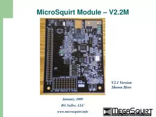
MicroSquirt Module – V2.2M V2.1 Version Shown Here January, 2009 BG Soflex, LLC www.microsquirt.info
MicroSquirt Module • MicroSquirt encapsulates pretty much everything that MegaSquirt has to offer, in a board the size of a business card. It would be nice to have this package for a true DIY setup… • For real engine experimenters, the MicroSquirt PCB is offered in a module format: • The exact same circuit of MicroSquirt is used (except ignition drivers, its logic-level output only on the module). • Ampseal is replaced with a 0.1” header, two rows of 25 pins (J2). All I/O are present on this header. Easy-to-source solution. • Additional processor I/O brought out on 2x5 header (J1). • Module size is 2.4 inches X 3.5 inches – credit-card sized! • Complete, tested module loaded with embedded Engine Control Firmware.
The MicroSquirt Module 2x25 – 0.1” J2 Header 2x5 – 0.1” J1 Header
J2 Header (0.150, 2.945) (2.2, 3.31) (1.8, 3.31) All Finished Hole Diameters Are 0.125” All Dimensions In Inches J1 Header (1.0, 0.205) (0.2, 0.205) (2.2, 0.205) Mounting Locations for Module
Pin 1,2 - +12V Battery Pin 3 – MAP Pin 4 - Serial Rxout Pin 5 – Coolant Pin 6 – Serial Txout Pin 7 – AccelLED/GPIO Pin 8 – Bootload Pin 9 – MAT Pin 10 – CANH Pin 11 – WarmLED/GPIO Pin 12 – CANL Pin 13 – TPS Pin 14 – VR in2(+) Pin 15 - Vref Pin 16 – SpareADC2/MAF Pin 17 – SpareADC1 Pin 18 – FLEX Pin 19 – Opto in(+) Pin 20 – Fidle Pin 21 – Opto In(-) Pin 22 – Fpump Pin 23 – VR In1(+) Pin 24,26,28,30,32 – Inj1 Pin 25 – VR In(-) Pin 27 – O2 Pin 29 – Tachout Pin 31 – SensorGND Pin 33,35,37,39,41,43,49 – PowerGND Pin 34,36,38,40,42 – INJ2 Pin 44,46 – IGN2 Pin 48,50 – IGN1 Module J2 Pinout See MicroSquirt documentation for signal descriptions: http://www.microsquirt.info
Pin 1 – PA0 Pin 2 – PE1 Pin 3,5 - Gnd Pin 4 - Alt-INJ1 Pin 6 – Alt-INJ2 Pin 7 – PT7 Pin 8 – Alt-CAM Pin 9 – PT6 Pin 10 – IACEnbl Module J1 Pinout
MicroSquirt Module • I/O Header is standard .100” (2.54mm) size, 2 rows of 25 pins (50 total circuits). Unpopulated. • Example receptacle header – Tyco/Amp 7-534206-5 • Matching pin header – Tyco/Amp 9-146254-0-25 • Standoffs are 7/16”, 1/4” Hex with 4-40 screws (Fascomp FC2103-440-A).
MicroSquirt Module • MicroSquirtModule is designed to be plugged into a Motherboard arrangement. This allows you to design your own custom PC board with any connector and accessory options you would like – here are some ideas: • USB connectivity • Bluetooth or Zigbee Wireless • On-board MAP and Baro sensors • On-board signal stimulator • Use of WBO2 modules • Connector for direct plug in (EEC-IV, L-Jet, GM, etc.) • Multiple modules for redundant setups, auxiliary fuel injectors, dual-fuel setup (gasoline+CNG), extended GPIO, etc. ….its up to you!
MicroSquirt Module – Eval Board • The MicroSquirt Module Experimenter’s board: • Mounts MicroSquirt module, breaks out all signals to screw terminals. For test and evaluation of the MicroSquirtModule. • Provision for MAP sensor, Serial DB9, and selection DIP switches. • Large user prototype area and user circuit for PIC18F processor, CAN, LEDs, serial transceiver, 5V power supply.