Download
1 / 47
1.88k likes | 4.31k Views
Mechanics of Composite Materials. Constitutive Relationships for Composite Materials. Ⅰ. Material Behavior in Principal Material Axes Isotropic materials uniaxial loading. 2-D loading. Where [ S ]: compliance matrix. Where [ Q ]: stiffness matrix. Isotropic Materials. Note:

E N D
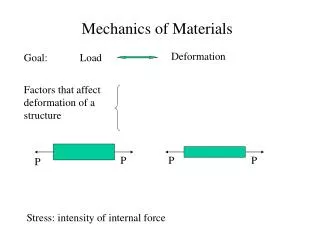
Constitutive Relationships for Composite Materials Ⅰ. Material Behavior in Principal Material Axes • Isotropic materials • uniaxial loading
2-D loading Where [ S ]: compliance matrix Where [Q]: stiffness matrix
Isotropic Materials Note: 1. Only two independent material constants in the constitutive equation. 2. No normal stress and shear strain coupling, or no shear stress and normal strain coupling. Examples: polycrystalline metals, Polymers Randomly oriented fiber-reinforced composites Particulate-reinforced composites
Transversely isotropic materials In L–T plane Principal material axes L: longitudinal direction T: transverse direction
Transversely isotropic materials In T1, T2 plane Same as those for isotropic materials: Principal material axes L: longitudinal direction T: transverse direction
Transversely isotropic materials Where EL: elastic modulus in longitudinal direction ET: elastic modulus in transverse direction GLT: shear modulus in L – T plane GTT: shear modulus in transverse plane LT: major Poisson’s ratio (strain in T – direction caused by stress in L – direction) TL: minor Poisson’s ratio And Note: 1. 4 independent material constants (EL, ET, GLT, LT ) in L – T plane while 5 (EL, ET, GLT, LT, GTT) for 3-D state. 2. No normal stress and shear strain coupling in L – T axes or no shear stress and normal strain coupling in L – T axes
Orthotropic materials For example in 1-2 plane 1.2.3: principal material axes
Orthotropic Materials Note: 1. 4 independent constants in 2-D state (e.g. 1-2 plane, E1, E2, G12, 12)while 9 in 3-D state (E1, E2, E3, G12, G13, G23, 12 , 13 , 23) 2. Nocoupling between normal stress and shear strain or no coupling between shear stress and normal strain
Question Ex. Find the deformed shape of the following composite: Possible answers?
Off-axis loading of unidirectional composite For orthotropic material in principal material axes (1-2 axes) By coordinate transformation , xyxy are tensorial shear strains
Let Then
Transformed stiffness matrix Where = transformed stiffness matrix
Transformed compliance matrix : transformed compliance matrix
Off-axis loading - deformation 1. 4 material constants in 1-2 plane. 2. There is normal stress and shear strain coupling (forθ≠0, 90˚ ), or shear stress and normal strain coupling.
Transformation of engineering constants For uni-axial tensile testing in x-direction ∴ stresses in L – T axes Strains in L – T axes
Define cross-coefficient, mx Similarly, for uni-axial tensile testing in y-direction
For simple shear testing in x – y plane stresses in L – T axes Strains in L – T axes
In summary, for a general planar loading, by principle of superposition
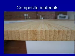
Micromechanics of Unidirectional Composites • Properties of unidirectional lamina is determined by • volume fraction of constituent materials (fiber, matrix, void, etc.) • form of the reinforcement (fiber, particle, …) • orientation of fibers
Volume fraction & Weight fraction • Vi=volume, vi=volume fraction= • Wi=weight, wi=weight fraction= Where subscripts i = c: composite f: fiber m: matrix
Conservation of mass: Assume composite is void-free:
Density of composite Generalized equations for n – constituent composite
Void content determination Experimental result (with voids): Theoretical calculation (excluding voids): In general, void content < 1% Good composite > 5% Poor composite
Burnout test of glass/epoxy composite Weight of empty crucible = 47.6504 g Weight of crucible +composite = 50.1817 g Weight of crucible +glass fibers = 49.4476 g Find Sol:
Longitudinal Stiffness For linear fiber and matrix: Generalized equation for composites with n constituents: Rule-of-mixture
Modes of Failure matrix-controlled failure: fiber-controlled failure:
Critical fiber volume fraction For fiber-controlled failure to be valid: For matrix is to be reinforced:
Factors influencing EL and scu • mis-orientation of fibers • fibers of non-uniform strength due to variations in diameter, handling and surface treatment, fiber length • stress concentration at fiber ends (discontinuous fibers) • interfacial conditions • residual stresses
Transverse Stiffness,ET Assume all constituents are in linear elastic range: Generalized equation for n – constituent composite:
Transverse Strength Due to stress (strain) concentration • Factors influence scu: • properties of fiber and matrix • the interface bond strength • the presence and distribution of voids (flaws) • internal stress and strain distribution (shape of fiber, arrangement of fibers)
In-plane Shear Modulus For linearly elastic fiber and matrix:
Analysis of Laminated Composites • Classical Laminate Theory (CLT) Displacement field:
Resultant Forces and Moments Resultant forces: Resultant moments: [A]: extensional stiffness matrix [B]: coupling stiffness matrix [D]: bending stiffness matrix
Laminates of Special Configurations • Symmetric laminates • Unidirectional (UD) laminates • specially orthotropic • off-axis • Cross-ply laminates • Angle-ply laminates • Quasi-isotropic laminates
Maximum Stress Criterion • Lamina fails if one of the following inequalities is satisfied:
Maximum Strain Criterion • Lamina fails if one of the following inequalities is satisfied:
Tsai – Hill Criterion • Lamina fails if the following inequality is satisfied: Where :
Comparison among Criteria • Maximum stress and strain criteria can tell the mode of failure • Tsai-Hill criterion includes the interaction among stress components
Strength of Off-Axis Lamina in Uni-axial Loading Maximum stress criterion Tsai-Hill criterion
Strength of a Laminate • First-ply failure • Last-ply failure