Download
1 / 74
1.08k likes | 1.98k Views
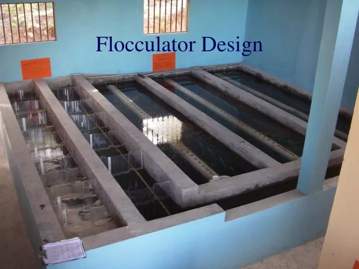
Flocculator Design. Overview. CFD analysis of hydraulic flocculators Ratio of maximum to average energy dissipation rate Inefficiency of energy use due to nonuniformity of energy dissipation rate The great transition at H/S=5 Flocculator Design

E N D
Overview • CFD analysis of hydraulic flocculators • Ratio of maximum to average energy dissipation rate • Inefficiency of energy use due to nonuniformity of energy dissipation rate • The great transition at H/S=5 • Flocculator Design • number of baffle spaces to obtain desired collision potential • Geometry of a baffle space to obtain desired energy dissipation rate
Top View W = Width of the flocculator channel S = Space between baffles L = Length of a flocculator channel S W L
Side View H = Water depth L = Length of the flocculator channel S = Space between baffles T = Thickness of the baffles B =Perpendicular center to center distance between baffles Exit to the sedimentation tank entrance channel Minimum water level 1.5 S Upper baffle Lower baffle S H Port from previous channel 1.5S L
Design Considerations • The length of the flocculator channels matches the length of the sedimentation tank • Width of the flocculation channel? • Minimum? ________________ • Material limitations (polycarbonate sheets or concrete) • Vary to optimize flocculation efficiency (function of geometry) • Need to determine • Head loss • Baffle spacing • Number of baffles Human width
Head loss around a bend?Vena Contracta • Sluice gate • 0.62 • Hole in a tank • 0.62 • Exit from a pipe • No Vena Contracta • Entrance into a pipe (next slide)
Entrance Losses Losses can be reduced by accelerating the flow gradually and reducing the change in direction
Vena Contracta(PVC ) Conclusions • Draw the most extreme streamline through the transition and determine the total change in direction • If the change in direction is 90°, then the PVC is approximately 0.62 • If the change in direction is 180°, then the PVC is approximately 0.622=0.4
Head Loss coefficient for a Baffle Head loss in anexpansion PVCBaffle is the contraction coefficient for a sharp 180º bend (0.622) Field measurements in Agalteca, Honduras suggest that 2.0 is a good value for KB and 0.41 is a good value for the contraction coefficient
How can we optimize the design of the flocculator? • The S to H ratio influences the efficiency of the flocculator • We used computational fluid dynamics (CFD) and the software FLUENT • We also used flow expansion analysis (total energy loss) and jet flow analysis (maximum energy dissipation rate) From rapid mix
Results of the CFD analysis: H/S = 4 S = 0.1 m H = 0.4 m V = 0.1 m/s 2d analysis The energy dissipation rate is an indicator of the collision potential
The Energy Dissipation Rate isn’t uniform • Ideally (for optimal efficiency) the flocculator would have a completely uniform energy dissipation rate • We can evaluate the efficiency of various designs as a function of H/S
Estimating the ratio of Definition of PJet Energy lost time True for large H/S where the jet fully expands before the next turn
extra Estimating the transition where the jet completely expands before going around the next baffle For H/S<5 = CFD results For H/S>5 We can set these two equations equal to find the value of the transition H/S (here equal to 5 given a *) *The estimate of PPlaneJet is lower than an axisymmetric jet. Further research is required to get a better estimate of the value of PPlaneJet
Results of the CFD analysis and our model equations e Is more uniform when H/S is between 3 and 5. ae relation between the maximum and average energy dissipation rate
Why a transition at H/S of 5? • Jets expand in width at the rate of approximately 1 unit in width per 10 units forward • Expansion length is 10(0.6S) • Expansion requires a distance of approximately 6S • The H/S transition is related to the distance required for the jet to fully expand 0.4S 0.6S
Flocculator Efficiency Which space between baffles is better, considering the uniformity of the energy dissipation rate? This space with very low energy dissipation rate doesn’t contribute much H/S = 4 H/S = 10
Flocculation Efficiency isthe flocculation efficiency given the non uniform energy dissipation rate Derivation of this result on next slide CFD results 2 3 4 5 6 7 8
Approximate value of for low H/S For large H/S From ae analysis Max value efficiency of energy use
Flocculator Design Challenges • It is uncertain if the CFD results for the slope of the efficiency line are correct because the CFD analysis predicted the loss coefficient to be 4 instead of 2 • Could be or could be • If the second equation is correct then the flocculator efficiency for large H/S is slightly lower than we are predicting here • The PPlaneJet value required to fit the CFD results is 0.225.
Collision Potential for one Baffle Space Collision potential is minimum of these two equations
A Simple Result For H/S<5* For H/S>5* • The collision potential depends primarily on the flocculator geometry • It is possible that the collision potential will be somewhat affected by the Reynolds number, but this effect, if any, will probably be small • We can design a flocculator for the maximum flow rate and be confident that the flocculator will also work for lower flow rates.
Collision potential per baffle • The collision potential per baffle is the minimum of the two equations • Small flows have small S, large H/S, and thus have less collision potential per baffle This plot is for the case of H=2
Why evaluate designs that are far from the optimum? • A more compact plant layout will be possible for small flows if we use a vertical flow flocculator with a high H/S ratio • For small plants the width of the channel will be determined by the need to construct the channel using humans (45 cm or more) • The space between baffles will be very narrow and thus H/S will be very high (for low flow plants) • Small plants will need longer residence time and more baffles to achieve adequate flocculation
Example • IfyB had a value of 1 m2/3 in the first channel, what value would the sum of yB be for the first channel? 17 Number of baffles= ______ Careful… Number of chambers = ___ yChannel= ________ 18 18 m2/3
Example: • How many spaces between baffles, (N) would be necessary if the flocculator has a depth of 2 m and if the space between baffles is 0.5 m? Assume a required collision potential of 100 m2/3. H = _______ S = _______ yB = _______ y = _______ N = _______ 2 m 0.5 m 1.52 m2/3 100 m2/3 66
Complaints? What is missing? • What was the flow rate for the previous example? • What was the width of the channels? • It seems that we are missing something • We only have been using the constraint of the target collision potential • We also need to use the constraint that we not break the flocs y
Turbulence or viscous shear can break flocs A floc in turbulent flow experiences a shear force due to the drag of the fluid on the floc caused by the velocity gradient The floc will also rotate and this will reduce the difference in velocity between the floc and the fluid
How do we quantify the turbulence level? • The energy dissipation rate, e, is a measure of the turbulence • It is in the regions of maximum e where the flocs are most likely to break mW/kg
ExtractingeMaxfromVelocity Gradient Design Guideline? • The value of the velocity gradient that was used previously for flocculator design had a range of 20 – 200 s-1 • The equivalent range for eMax is 0.8 – 80 mW/kg Kinematic viscosity Velocity gradient Ratio of the maximum to the average energy dissipation rate (2 for H/S<5)
Extracting eMax from Fluid Velocity Design Guidelines? • Traditional guidelines for velocity are between 0.1 and 0.3 m/s. • Equivalent to of 1 to 30 mW/kg
Laminar flow: Floc diameter vs. average e The average floc size as a function of average e in a laminar flow tube flocculator. Floc diameter is independent of the collision potential for large collision potentials. Can these flocs be captured by plate settlers? _________ Yes! -Ian Tse Spring 2009
The influence of eMax • The value of eMax determines the maximum size of the flocs • eMax of 10 mW/kg is the current (as of 2011) AguaClara standard • We are considering increasing eMaxto 30 mW/kg to reduce sedimentation in the flocculator (but this will require more head loss in the flocculator) • Conclusion as of Fall 2013 is to keep the energy dissipation rate at 10 mW/kg
S W Relationship between geometry and energy dissipation rate A For H/S>5 For H/S<5 From CFD and jet analysis
Calculate Baffle Spacing • Choose eMax (perhaps 10 mW/kg) • For small flows the baffles need to be easily removable because the spacing is less than the human dimension • Set channel width based on constructability • Calculate spacing of baffles Use max of these equations
Design Considerations • Design is dominated by material size and constructability • Channels must be wide enough to be constructible (45 cm) • The material used for flexible plastic baffles is expensive and waste should be minimized
Example Design: Flocculator with a flow of 10 L/s • Assume H = 2 m, W=50 cm, eMax =10 mW/kg • Let’s assume that H/S >5 (we will check this!) H/S >5
How many Baffle Spaces? Calculate the collision potential per baffle space For H/S>5 Assume y = 100 m2/3
Calculate the Head Loss For each baffle space
Flocculator residence time Residence time between two baffles Residence time in the flocculator Number of baffle spaces Improve this estimate by taking head loss into account! What is the average depth of water in the flocculator?
Design steps:Given H,W, Q, eMax, and y For H/S>5 For H/S<5 • Calculate S • Calculate yB • Calculate the number of spaces and head loss
extra Small Flocculator Design Let PHS=5 Square Keep flow passage square to minimize coagulant loss to walls
extra Top view of Low Flow Flocculator Floc Tank Channel Ferro-cement or other rigid material in slots in the wall Polycarbonate baffles PVC pipe (1/2”) PVC pipe spacers blocking 60 of flow area
Transition Flow Ratewhere H/S=5 ~5 Set the 2 equations for S equal For 10 mW/kg, H=2m, W=0.6 m, then Q=42 L/s
extra Vertical vs. Horizontal Flow • For small plants… • Horizontal flow flocculators are shallow and thus need to be elevated so the water level in the flocculator matches the sedimentation tank • Vertical flow flocculators take up less space (smaller footprint) because they are deeper • For large plants… • Horizontal flow can be made as deep as the sedimentation tank and are preferred because they are easier to drain
extra Vertical vs. Horizontal Revisited • Vertical flow flocculators are somewhat difficult to drain and clean • For large flows, vertical flow flocculators have channels that are wider than they are deep • Why not switch to horizontal flow flocculators for large flows? • Why not use horizontal flow for all flows?
extra Horizontal flow for all flows? 5 Lps plant with horizontal flocculator This is a bad alternative because concrete slab floor, roof, walls, and land are all expensive!!!
extra Horizontal Flow Flocculator • Depth of the water is known (W) • Width of the channel is H (unknown) • Use H/S of 3 as a constraint • Solve for S and then finally solve for H Eliminate H with H/S
extra Minimum Flow rate for Horizontal Flocculators? • The construction constraint requires that baffles be at least 45 cm (we will use 60 cm) apart (S). • The depth of water is W • Use an H/S of 3 and calculate H • Solve for Q
extra Minimum Flow rate for Horizontal Flocculators? • The minimum flow rate for a 2 m deep tank is about 250 L/s • If we build shallower flocculators then we could design horizontal flocculators for lower flow rates (perhaps as low as 50 L/s), but this would increase plant size • Water surfaces (sed and floc) must match!