Download
1 / 13
130 likes | 292 Views
Introduction. For new applications : fibre-radio systems optically supplied microwave antennas There is a need for microwave photonic functions. Optical switching matrixes. Emitters. Receivers. microwave. microwave. optical fibre. optical fibre. Axially coupled lasers : fabrication.

E N D
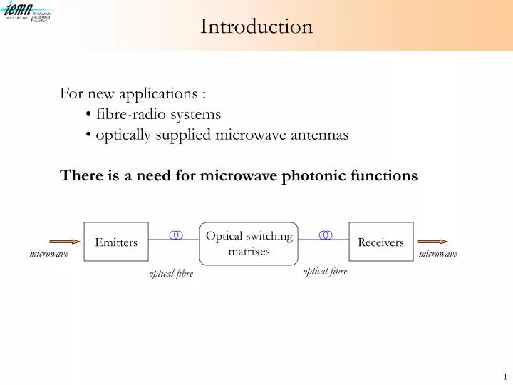
Introduction • For new applications : • fibre-radio systems • optically supplied microwave antennas • There is a need for microwave photonic functions Optical switching matrixes Emitters Receivers microwave microwave optical fibre optical fibre
Axially coupled lasers : fabrication GaInAs GaInAs InP p + Active layer (MQW) InP n + Substrate InP SI InP p+ InP p+ At IEMN and Tempere University of Technology Fabrication on semi-insulating substrate Fabrication on N+ substrate Perot-Fabry lasers European TMR project
Axially coupled lasers: microwave experiments f = 11,4 GHz • optical generation of a microwave • signal (beating of the optical modes • in a photodetector) • tuning of the frequency with • bias currents • observed on the frequency response
The Dual Mode Laser structure elementary sampled grating Sampled grating structure P Contact 10 µm 80 µm P+ N+ N Contact It is a sampled grating DFB laser 710 µm long device: - 7 DFB sections (10µm) - 8 FP sections (80 µm) - 2 end DFB sections (40 µm) It is also a DFB laser with a reduced coupling coefficient
Digital Optical Switch No carrier injection BPM Modelling Carrier injection A Y junction unbalanced by injection of carriers
Variation de la puissance du signal hyper à 9GHz en fonction du courant injecté dans le DOS 0 0 5 10 15 20 25 30 35 40 -20 -40 P (dBm) -60 branche éteinte branche commutée -80 58 dB ! -100 -120 I (mA) Département Hyperfréquences & Semiconducteurs
mesure du bruit de phase - modulation 9 GHz 0 0,00E+00 2,00E+05 4,00E+05 6,00E+05 8,00E+05 1,00E+06 1,20E+06 -10 -20 référence moyenne commutation moyenne P -30 -40 -50 -60 fréquence relative Département Hyperfréquences & Semiconducteurs
High power photodiodes : possible solutions • Travelling-Wave Photodetector • Increased absorption volume • Electrodes = 50 microwave line • Optical and microwave velocity matching • Uni Travelling Carrier Photodiode • Absorption in P+ GaInAs layer (no field) • Transit of photogenerated electrons by diffusion (base) and drift (collector)
New concept : diluted multimode waveguide P+ InP nid GaInAs N+ GaInAsP N+ GaInAsP N+ InP 1.3 µm or 1.55 µm N+ GaInAsP N+ InP N+ GaInAsP N+ InP N+ GaInAsP N+ InP N+ GaInAsP N+ InP • Good coupling to the fiber- One quaternary GaInAsP and InP layers- Specific waveguide half lens
Diluted multimode waveguide : optical behaviour Typical behaviour of the optimized multimode diluted waveguide Photodetector behaviour Vertical scales dilated
Experimental results • Device fabricated at Opto+ (Alcatel) • 11µm thick epitaxial structure (MOCVD) • l=1.55µm : Max Resp=1.06A/W • l=1.30µm : Max Resp=0.86A/W • -1 dB misalign. tolerance = 6.5 µm • Influence of optical polarisation : lower than 0.1dB in all cases • Cut-off frequency > 3GHz @-3V • Work in progress to get • millimeter wave devices • High reliability 200°C / -10V / 1030 hours After Before
Résultats des transmissions 32-QAM le câble coaxial (référence) 1km MMF le diagramme de constellation le diagramme de l ’oeil Département Hyperfréquences & Semiconducteurs
Réponses fréquencielles de MMF 2 0 -2 -4 -6 -8 -10 >80% des fibres intra -bâtiment < 300m 100m 500m réponse, dB 1km 0 2 4 6 8 fréquence, GHz Département Hyperfréquences & Semiconducteurs