Download
1 / 26
260 likes | 410 Views
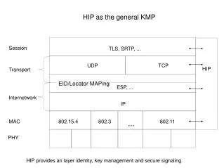
Model-based Adaptive Product and Process Engineering Work Package 2 Evatronix & advICo Use Case: Collaborative IP-based SoC design Pilot 3 demonstration and D15. USB PHY design challenges in MAPPER. Needed experts from two different designers’ words: analog and digital

E N D
Model-based AdaptiveProduct and Process EngineeringWork Package 2 Evatronix & advICo Use Case:Collaborative IP-based SoC designPilot 3 demonstration and D15
USB PHY design challenges in MAPPER • Needed experts from two different designers’ words: analog and digital • The design environment is distributed (2 companies, 3 locations) • Problems with interoperability of current design tools (different domains, different file formats)
Evatronix and Advico workflows Each company has well defined own design flow advICo Design Flow Component specification Development Verification Product preparation
Evatronix Design Flow advICo Design Flow Analog and Digital Block integration Distributed design and verification between Advico and Evatronix But common USB PHY design flow was a challenge
Distributed design and verification between Advico and Evatronix But common USB PHY design flow was a challenge
Pilot 3 USB-OTG-PHY design coverage Integration &Verification of whole USB PHY design was a scope of the Pilot 3
Pilot 3 Distributed design and verification between Advico and Evatronix Demo
Pilot 3 – step 2 Digital waveform view
Pilot 3 – step 2 Analog waveform view
Deliverable D15 • Visual knowledge modeling in the field of Electronic Design Automation • Towards distributed collaborative design of electronic systems – USB PHY IP component development • Collaborative refinement of design specification through virtual meeting – Pilot 1 • Distributed design and verification at Evatronix – Pilot 2 • Distributed design and verification between Evatronix and advICo – Pilot 3 • Design task patterns • Contributions from ethnography
Active knowledge models in WP2 • Evatronix (digital) and advICo (analog) design process • enterprise architecture (POP*) • joint A/D design flow (USB PHY) • pilot definitions • design task patterns • CVW interface
MAPPER collaborative infrastructure deployed in WP2 • Tool integration with TRMS v. 2 • CURE workspace • Metis modeling • GUIs: CURE, CVW
TRMS development path TRMS 1 E-Colleg result application ANTS transport mechanism partial firewall crossing TRMS 1.1 initial version for MAPPER application own transport mechanism no firewall crossing 2003 TRMS 1.2 developed in MAPPER applet own transport mechanism service-based functionality 2005 TRMS 2 new architecture application http/https transport mechanisms firewall crossing 2006 2007
TRMS achievements in MAPPER • new architecture developed (old terminology kept) • transfer based on standard https or http protocols • all functionality based on Web services (supporting MAPPER integration) • both applet and application versions available • deployed in pilots 2 and 3
Distributed design and verification of USB PHY design at advICo and Evatronix Conclusions • METIS – models of each company design process allow to develop the best common design process for this special (from each company perspective) USB PHY design • CURE – As this interface didn’t require any additional effort from end users to setup it, and it can be used almost everywhere where internet access is – this is ideal environment which can integrate various design tools. • TRMS – possibility of invoking it just from web browser, implemented security, remote invocation different design tools. All these features support automatisation of our design process. TRMS helps us use our tools more efficiently and accelerates our design work