Download
1 / 30
330 likes | 664 Views
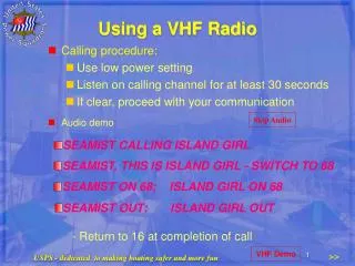
Building a FOXHOLE Radio. LIMARC PRESENTATION November 2013 Ron P Milione Ph.D. ron.p.milione.ctr@us.army.mil.

E N D
Building a FOXHOLE Radio LIMARC PRESENTATION November 2013 Ron P Milione Ph.D. ron.p.milione.ctr@us.army.mil
GI's, during World War Two, These radios were essentially crystal sets that used blue razor blades for detectors because crystals were almost impossible to obtain under the conditions the G.I.s faced in those days. In the early 1940s, tube type portable radios were fairly large and used short-lived, expensive batteries that would have been hard to find in the field. Also, the Germans had sensitive, radio direction finders that could pick up the local oscillators of superheterodyne portable receivers. They could use these devices to “home in” on the locations of the Allied emplacements in order to direct artillery and aircraft fire. Because of this, it was forbidden to use portable superhets on the front.
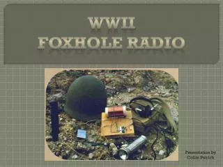
Background During World War II, GIs were often isolated from hearing the day- to- day news of what was happening beyond their barracks. A few clever radio- deprived GIs figured out that they could use miscellaneous scrap metal and junk to construct a simple radio. Word spread, and soon scores of soldiers were creating their own radios. Amazingly enough, these radios did not require electricity or any other power source. Here is a chance for you to take a step back in history.
Background Historically, razor blades were often blued steel. A non-linear resistance property of the blued steel of razor blades, foreshadowing the same property that would later be discovered in semiconductor diode junctions, along with the ready availability of blued steel razor blades, led to the use of razor blades as a detector in the crystal set AM radios which were often built by soldiers during World War II.
Background Among those was young Lieutenant Paul M. Cornell, W8EFW, who wrote of a design he used in the Pacific in 1945. It was one of the first such articles that mentioned using a pencil lead for a contact. Mr. Cornell article was printed in the September, 1945 issue of QST Magazine!
The Real Background A Foxhole Radio is a radio built by G.I.s during World War II. The foxhole radio differed from the crystal radio. A razor blade and pencil were used as a diode in a foxhole radio while a piece of crystal is used as a diode in a crystal radio. The Foxhole Radio is like a crystal set in that it does not require an external power source. The radio is powered by the radio frequency that it receives. This made the Foxhole Radio ideal for the prisoner of war (POW). Prisoners of war made these radios to keep up with current events. Generally, this radio is called so because of the foxholes-small man-made underground shelters used along defensive lines during the war, and so, any radio built during the war can be regarded to be a foxhole radio, but ideally, this radio does NOT use semiconductors and does not have access to a power supply. In 1942 Lieutenant Colonel R. G. Wells was a prisoner of war in Japan. Wells built a foxhole radio because he lacked information about the international situation. The whole POW camp had a genuine craving for news by whatever means according to Wells
The Real Background Designs Foxhole radios were built using numerous designs. Most of them used a razor blade which had a wire running from each blade between the headphone terminals and antenna with a pencil lead sitting on the blade. Most of these wartime sets did not have a slider/tuner arm. Without the tuner they could only tune in to one frequency. Richard Lucas, a POW in Vietnam, constructed a radio in camp and built his own earphones. Richard built his earphones by binding four nails together with cloth then winding wire and dripping wax over the turns. After about ten layers of wire he placed it in a piece of bamboo. A tin can lid was placed over the coil of wire. The listener connected the improvised earphone to the Foxhole Radio and received three radio stations. Best listening was at night, according to Lucas!
The Real Background Operation The incoming radio frequency send electricity back and forth in the coil. The electricity must be fixed so that its changes will go in one direction to the earphones. The safety razor and lead from the pencil act like a gate. When the blade's steel and pencil's lead come in contact with each other they will only allow electricity to go in one direction. After the electricity goes through the steel and lead it goes into the headphones which is a high impedance.
The Gear List……. GEAR LIST • Vintage- style fahnestock clips or paper clips • 10 wood screws or thumb tacks • 10 washers for the screws • Needle- nose pliers • Wire hanger • Wooden board (a 1⁄2- inch- thick pine board is best) • Coil form (you can use a cardboard toilet paper roll that’s at least 13⁄4 inches in diameter—2 inches is best) • Number 2 lead pencil • Single- edge safety razor (preferably “blued”; see step 13) • Geranium diode—1N34A (from Radio Shack), optional • 40 feet of #22 AWG coil or magnet wire • 1 foot of #26 wire • 100 feet of antenna wire or an antenna kit • Sand paper • Crystal earphone • Safety pin • Screw driver • Spray lacquer
Let’s Construct One STEP 1: Cut the wooden board to which your radio will be attached. The exact size is irrelevant, but it should be at least 6 × 6 inches to accommodate all the parts. STEP 2: Create coil form. This is the tube around which you are going to wrap about 40 feet of copper wire. A toilet paper role will do, but it might be a bit flimsy. If you can get your hands on thicker tubing, such as the type used for gift wrapping paper, it will be more solid. In my set I used a 4- inch wide tube. STEP 3: Punch four tiny holes in the tube. The two holes at each end should be about 1⁄2 inch from the end and about 1⁄4 inch apart. The two holes on each end should run width- wise to the ends.
Let’s Construct One STEP 4: Wind the wire tightly around the coil form. This may be accomplished in many ways, but ultimately wrapping it by hand is best. It is very important that the coils be wrapped neatly next to each other. Note: Allow for about 6 inches of excess wire on the right side of the tube. I used magnet wire, which is a copper or aluminum wire covered with thin insulation. If you go to a place like Radio Shack, ask for #22 AWG (American Wire Gauge). It should be between 100 and 125 turns.
Let’s Construct One STEP 5: Tighten the coil manually by gripping it between both hands and rotating your hands in opposite directions. STEP 6: Spray the coil with lacquer to help keep the form wrapped tight. Allow it to dry.
The radio components STEP 7: Attach the coil tothe board. Use either two thumb tacks or two small screws. The excess coil wire should protrude from the front side of the tube, closer to the board, rather than from the top of the tube. STEP 8:Attach four wire clips to the board—two on each side of the board below the coil. They should be about 41 ⁄2 inches apart from each other width- wise along the coil and about 11 ⁄2 inches apart from each other on each side of the board. The top clips should be about an inch below the coil.
The GI Radio Components TIP: You can substitute paper clips for the clips and thumb tacks for the screws. The idea is to be as innovative as the GIs in the field! STEP 8: Attach four wire clips to the board—two on each side of the board below the coil. They should be about 41 ⁄2 inches apart from each other width- wise along the coil and about 11 ⁄2 inches apart from each other on each side of the board. The top clips should be about an inch below the coil.
Steps STEP 9: Make the tuner slider by cutting 7 or 8 inches of wire from a wire coat hanger. If the hanger has any type of coating on it such as paint, lightly sand it to improve contact points and reception.
STEP 10: Using needle- nose pliers, bend a loop around the bottom end of the tuner slider. This loop will be wrapped around a screw and washer, so bend it accordingly. You may want to attach a knob or ball of tape at the top end of the slider as this is where your fingers will move the slide later for tuning. About 3 inches below the coil, in the middle of the board, attach the slider to the board by placing it on top of two washers. Then screw it to the board firmly but not so tight that it inhibits the movement of the slider. The hook- up wires should go under the washers for all contact points.
STEP 11: Attach the safety pin, which will be the detector contact, to a 2- inch piece of bare lead by bending the pin open about 90 degrees (on the clasp side—see illustration) and wrapping the pin side with #26 wire. Sharpen the end of the lead with a razor. STEP 12: Attach the safety pin to the board, using a washer and screw, in the lower right- hand corner. Attach a wire between the safety pin head and board with a washer and screw and wrap wire to the lower right clip, which will ultimately be one of the headphone attachments clips. The tip of the lead will ultimately come in contact with the side of the razor.
STEP 13: Attach the razor blade, which will act as the radio’s crystal. If you use a standard single- edged razor, it will need to be “blued” or heat treated. To do this, attach it to some pliers in a vise and heat it with a torch. (If you don’t have a torch, you can purchase one that’s ready to go from a hobby shop.) Bend the safety pin so that the tip touches the razor’s surface. FYI During World War II, standard- issue razors were blued because they remained sharper longer.
STEP 14: Attach the rest of the wires according to the illustration. If any of the connections or contact surfaces are lacquered or painted, sand them lightly. STEP 15: Attach a long wire to use as an antenna to the lower- left clip. The longer and higher, the better—use between 50 and 100 feet of wire of any type. Radio Shack sells some really great antenna kits for very little money. I have found that it works fairly well to attach the antenna high up on a tree or pole. Your radio must have a ground wire. Plumbing pipes work as do flag poles. Experiment with different metal contacts. Attach the ground wire to upper- left clip.
Demo Time – Post Operations These were the “Blue Blade” type that had a blue oxide finish, and that finish, in contact with an ordinary pencil “lead”, made a point-contact rectifier. This served the purpose of the “crystal” and “cats whisker” of early crystal radios; it permitted current coming in from the antenna to flow in only one direction. This served to “build up” the antenna signal to a level that could be heard in the earphones by a process known as “detection”. An attached coil of enamel-insulated wire acted along with the antenna wire capacitance to produce a tuned circuit, tuned approximately to the radio frequency band of interest.
Demo Time – Post Operations All that was then required was a long piece of wire for an antenna (that barbed wire fence or a length of infantry telephone “commo wire” was perfect). Plus a ground connection consisting of a metal tent stake or bayonet stuck into the moist soil. A few other bits such as a safety pin, a piece of bamboo or toilet paper cardboard tube for the tuning coil form, a piece of wood from that ammo crate for a chassis, a few screws, thumbtacks or nails and a paper clip to make a “tuner”. The below photos illustrate the basic idea. The radio is adjusted for best signal by moving the pencil point to different spots on the razor blade to find the “sweet spot” where rectification takes place. (The signal will sound louder). Then adjust the paper clip tuner along the coil turns (put on as many turns as you can – 100 +) to tune and optimize the signal you want to hear. It’s a bit trial-and-error to produce a good signal and it depends a lot upon the height and length of your antenna, the quality of your ground connection, the frequency and local strength of your target station.
Demo Time – Post Operations You need a high impedance earphone to convert the electrical signals to sound and the high impedance insures that the phones won’t load down the circuit.