Download
1 / 49
490 likes | 646 Views
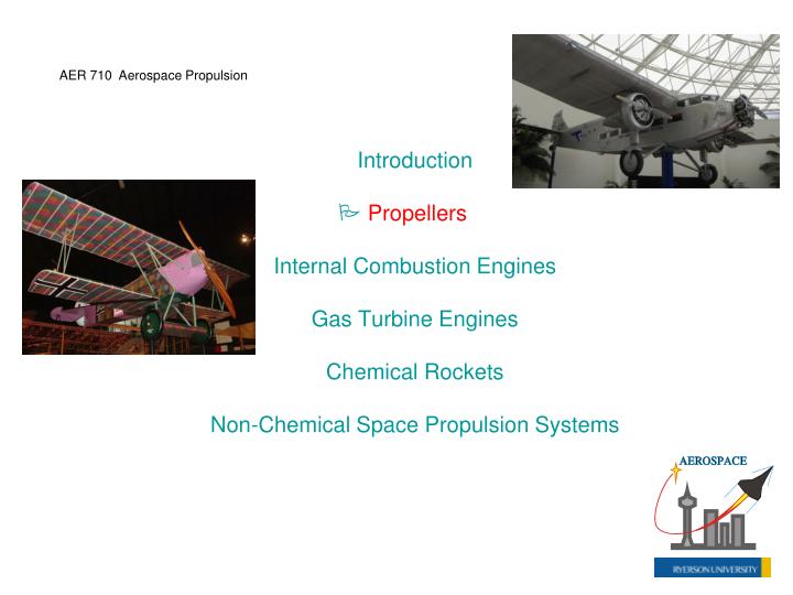
AER 710 Aerospace Propulsion. Introduction Propellers Internal Combustion Engines Gas Turbine Engines Chemical Rockets Non-Chemical Space Propulsion Systems. C-130. Nieuport N.28C-1. Introduction to the Propeller.

E N D
AER 710 Aerospace Propulsion Introduction Propellers Internal Combustion Engines Gas Turbine Engines Chemical Rockets Non-Chemical Space Propulsion Systems
C-130 Nieuport N.28C-1
Introduction to the Propeller • The rotating blade of a propeller shares similar characteristics to a wing passing through the air • A propeller blade generates thrust F through an aerodynamic lift force component, demands an engine torque Q to overcome aerodynamic drag, and will stall if the local resultant angle of attack of the blade exceeds max • Additional factors: trailing vortex generation, tip losses, compressibility
Forces acting on wing airfoil section (above) and propeller blade section (below)
Actuator Disk Theory • For evaluation of propeller performance, one can apply a simple analytical approach using the principle of linear momentum conservation, and treating the propeller as an actuator disk where there is a step increase in pressure
Thrust generated by disk: Alternatively: Bernoulli’s eq. applied from upstream to front of disk:
Similarly, downstream of disk: Noting po = p3 , and V2 = V1, via subtraction one gets: Conservation of mass, incompressible flow: A3V3 = A1V1 Substituting from earlier:
and which gives the simple result: Define propeller-induced velocity w such that: and so for thrust,
Ideal power required: or Since power from a piston or turboprop engine is relatively constant at a given altitude, one can expect the thrust to drop as the airplane picks up airspeed, according to this correlation. If one wishes to find w as a function of F, from earlier:
giving Ideal static power (Vo = 0): Ideal propeller propulsive efficiency: or via substitution (q is dynamic pressure):
Actual propeller propulsive efficiency, in terms of useful (thrust) power and engine shaft power PS: Correction factor, less than 1, for ideal power estimate: Variable-pitch propeller better able to approach the ideal power requirement, as compared to a fixed-pitch propeller, in accommodating different flight speeds and altitudes.
Momentum-Blade Element Theory • Logically, the next level of analysis would look at a given propeller blade’s aerodynamic performance from hub to blade tip • one can discretize the blade into a finite number of elements, while applying momentum conservation principles
Schematic diagram of a three-bladed propeller, and framework for discretizing an individual blade for analysis
Increment of thrust: Resultant velocity:
Increment of torque: Increment of lift: Increment of drag: Overall resultant velocity:
Induced angle of attack: Airfoil lift coefficient: Airfoil drag coefficient: C < C,min C,min < C < C,max > max
Via substitutions, increment of thrust: where B is number of blades. Borrowing from actuator disk theory: Equating the above relations, one arrives at:
Overall propeller solidity: Local solidity: x = r/R Advance ratio: where n isthe prop shaft rotation speed (rps). Nondimensional velocity ratio:
Also: VT = R Substituting from earlier: Applicable solution for induced angle of attack via the above quadratic eq. gives:
Propeller thrust coefficient: Propeller power coefficient: Incremental thrust no. of blades: Incremental power no. of blades:
Note: Thrust coefficient: Power coefficient:
Momentum-Blade Element Theory (Summary) • The above equations for CT and CP can be integrated from the hub station (x = xh) to the blade tip (x = 1) using a numerical approach as one moves along the blade of varying and c, calculating the various pertinent parameters (C, Cd, i , etc.) in conjunction
Power Thrust
Propeller Propulsive Efficiency • Define as useful thrust power over overall shaft power: Also, via substitution: A variable pitch propeller will have better efficiency over the course of the flight mission, relative to a fixed pitch prop.
Chart illustrating propeller propulsive efficiency for an example propeller
Compressibility Tip Loss • Depending on the blade airfoil section design, drag divergence (compressibility) effects will become evident when the propeller blade’s resultant tip speed VR,tip exceeds a local flow Mach number Matip of around 0.85 (critical value, Macr) • As a result, one would not typically be cruising at much greater than a flight Mach number Ma of around 0.6
Blade tip Mach number: Dommasch correlation: Modern high-speed blades may be thinner, and swept or curved along the blade length, to mitigate the issues with compressibility and compression wave development at higher local flow Mach numbers
Activity Factor • Activity factor (AF) is a design parameter associated with the propeller blade’s geometry. The more slender the blade (larger radius, smaller chord), the lower the AF value: Typically see higher AF props on turboprop engines.
Blade Number • One has the option of setting the number of blades, B, for a given application. While one has a minimum of 2 blades to choose from, one can presently go as high as around 8 blades on the high-performance end for an unducted propeller • On occasion, one also sees the use of two contra-rotating rows of blades, to get more thrust delivery from one engine
Photo of Fairey Gannett carrier-borne anti-submarine/AEW aircraft, employing two contra-rotating rows of 4 propeller blades each on a co-axial shaft setup, powered by a 3000-hp Armstrong Siddeley Twin Mamba turboprop engine
Helicopter Rotors • helicopter rotors (main and tail) share a number of similarities with airplane propellers • analysis done above for propellers can be applied to rotors • orientation of the rotor disk will be somewhat different from that of the propeller, with respect to the resultant incoming air flow • Main helo rotor produces lift + thrust
- rotor blade will advance into the air flow when in forward flight, and then retreat during the other half of the rotational cycle CH-47
tail rotor primarily controls yaw forces and moments [primarily main-rotor-induced torque] on the helicopter, if only having one main rotor • a tandem-rotor helicopter, with two contra-rotating main rotors, would not need a tail rotor
ducted tail fan is an alternative to the conventional • tail rotor HH-65 Dolphin
NOTAR No Tail Rotor (Using Coanda Effect)
The amount of lift generated by a main rotor is controlled by two means: a) the engine throttle setting for desired level of main rotor rotational speed, and b) collective pitch setting, which sets the angle of incidence of the main rotor blades collectively to produce the desired uniform lifting force on the vehicle (e.g., higher lift required, a higher blade incidence angle setting is needed, for the same rotor rotational speed) • Rotation of the vehicle’s body in pitch or roll or some combination thereof is largely via the cyclic pitch setting of the main rotor, whereby the individual main rotor blades will have their incidence vary as they complete a given revolution about the vehicle, depending on the desired direction of the rotational moment
Operations of swashplate (item #2, 4 above) for cyclic control
The schematic diagram illustrates a conventional main rotor mast (rotorhead), with the hub above the mast connecting the rotor blades to the drive shaft in a fully articulated design (hinged); a swashplate approach is being used to control the effective main rotor disk deflection and tilt direction thereof
Fully articulated, a.k.a., hinged (horiz. + vert.) rotor head above (vs. rigid, a.k.a., hingeless)
Hybrid Aircraft Designs • In order to improve range performance over a conventional helicopter, one will see tilt-wing and tilt-rotor designs for V/STOL (vertical/short takeoff & landing) applications Tilt-rotor V-22 Osprey