Download
1 / 27
290 likes | 299 Views
The Swift Mk. 5 single-seater suborbital spaceplane. Rick Newlands, Chairman, Aspirespace. Mission objectives:. Manned suborbital flight to 120 Km (Space) over the U.K. (Scotland). One-person craft with large windows. Ability to abort from any point in the flight.

E N D
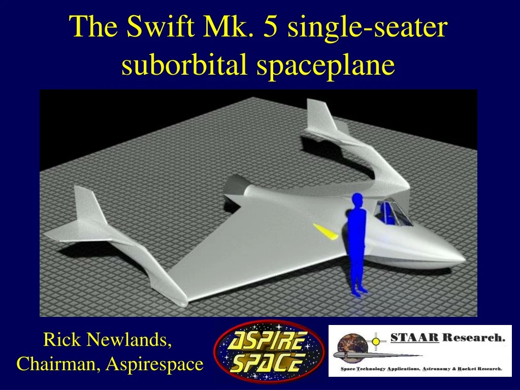
The Swift Mk. 5 single-seater suborbital spaceplane Rick Newlands, Chairman, Aspirespace
Mission objectives: • Manned suborbital flight to 120 Km (Space) over the U.K. (Scotland). • One-person craft with large windows. • Ability to abort from any point in the flight. • Large choice of landing sites. • Lower cost. • Use amateur/hobbyist rocketry and homebuilt aircraft technology and experience. • Higher and faster than Spaceship 1 or 2. • As safe as is feasibly possible.
Air-launch from a gas balloon • Air-launch is safer than launching from the ground. • Ground launch facilities not required. • Larger number of abort options: time to sort your life out during the fall from altitude. • Rocket portion of the flight can occur over the sea (lowest population density) as there are too many people on the land to fall on. • Land or sea recovery. • For a launch over the U.K. an air launch from a gas balloon out to sea is the best option.
Rockoons • Silicon-based life-form or rocket launched from a balloon. • Effective 1st stage takes rocket above 90% of the atmosphere: big reduction in rocket energy lost to drag. • Launch in near vacuum: big improvement in rocket nozzle performance leads to significantly greater rocket efficiency. • 1/6th propellant requirement as compared to ground launch. • Mass ratio required is only about 2: i.e. only half the launch mass need be propellant mass. • Ability to vary launch altitude to suit less precise mass ratio estimates. • Rocket engine throttling not required. • Low air loads (later): fat/draggy fuselage allowed.
Vehicle choice • Capsules rejected. • Need plenty of abort options. • Need to be able to thoroughly flight-test the vehicle before the first rocket-powered ascent. • Ascend over the sea, but land recovery preferred over splashdown in sea: glider required. • Use amateur rocketry experience: rockets, boost-gliders. • Rocket-boosted glider the best option.
Equivalent airspeed (EAS) • Aerodynamic loads on the vehicle (lift, drag, ‘hull pressure’) depend on Equivalent Airspeed (EAS) (this is also the speed shown on a properly calibrated airspeed indicator; ‘Indicated Airspeed’). • EAS is equal to the real vehicle velocity (True Airspeed, TAS) only at sea-level; is less than TAS with increasing altitude:
Launch altitude: • Want low EAS throughout ascent: max of 140 knots (typical light aircraft airspeeds) • Want high enough EAS for aerodynamic control right up until motor burnout (min of around 30 knots) • Want high enough TAS at burnout to reach 120 Km apogee (assumes 4 gee max thrust) • These constraints dictate a launch altitude of about 70,000 feet (from trajectory sims)
Vehicle design • Minimise ’G’ loads: large wing area required. • Maximise number of landing sites, land on grassy fields or sandy beaches: large wing area required. • Want cheap and simple U.K. CAA certification: one-man VLA (Very Light Aircraft) homebuilt, or microlight. • Automatic (autopilot) ascent. • Auto-stable (hands-off) re-entry. • Manual post-re-entry glide. • Good view out of windows. • Electrically-powered irreversible controls. • Simple propulsion system.
Flat windows • Primary payloads are the pilot, and the windows. • Windows are non-structural, and not reacting internal cabin pressure: separate transparent plastic inner pressure cabin (part of which is shown here in light transparent red). • Windows are purely a transparent aerodynamic covering. • Flat glass panels of high-temperature-resistant tempered glass considerably cheaper than curved panels.
Irreversible controls • With design of SpaceShipOne and Two, decision was taken to use a pneumatic system to actuate the feathering mechanism. • I immediately thought that that wasn’t non-reversible. • Sadly, during a test-flight, the pneumatic feathering system on Spaceship Two did ‘unwind’ and it led to the breakup of the craft and a pilot was killed. • An electric motor linked to a screw-jack is the better way to move a feathering system. • Similarly, geared electric servos on all control surfaces.
Propulsion system • Nitrous hybrid is safest form of propulsion found in amateur research: simple, rugged, and (almost!) idiot-proof. • Based upon the Aspirespace H2 engine: N2O (subcritical nitrous oxide) and High-Density PolyEthylene (HDPE) • Self-pressurising. • Low nozzle temperature. • Regressive burn: ‘self throttling’. • Engine can be stopped by shutting off the nitrous supply. • Reduced C.G. travel during engine burn. • Dumping the nitrous jettisons 7/8ths of the propellant mass. • Twin combustion chambers for simplicity, but a single post-combustion chamber and nozzle.
Hybrid vectored thrust options • Steerable ‘flex’ nozzle: mechanically very complex and one-shot only, can’t pre-test. • Liquid injection: possible option but difficult to pre-guess quantity of liquid required. • Jet vanes in exhaust: simple, but always on, causes loss of thrust. • Jetavator: looks like a napkin ring encircling the nozzle exit, tilt to deflect thrust. Only ‘on’ when required, otherwise no loss of thrust. • Jetavator selected as best option.
Aspects of very high altitude flight 1 • At low altitudes, aircraft have good dynamic stability: • Vehicle rotations ( ) cause an extra angle of attack on the fins/tailplane which resists the rotation, and damps it out: ‘aerodynamic damping’. • This damping decreases as True airspeed increases: Extra angle of attack = • So at very high altitudes (low EAS but high TAS) there is no rotational damping.
Aspects of very high altitude flight 2 • Aircraft difficult to fly, because there is no damping to prevent high rates of rotation from building up: ‘feels like driving on ice’. • Real danger is lack of roll damping; rapid roll rate can quickly build up: ‘corkscrewing’, as happened to Spaceship One. • Introduce rotation-rate sensors (rate gyros) into the control servos as feedback to limit rotations; make rotation rate proportional to joystick movement.
Exposure to Space (is bad!) • Lack of oxygen (hypoxia): rapid loss of consciousness, wear an oxygen mask. • Decompression illness: at altitudes over 18,000 feet. Nitrogen bubbles out of the blood and causes ‘the bends’. Pre-breathe oxygen for a few hours before liftoff to purge blood of dissolved nitrogen. • Ebullism: altitudes over 63,000 feet - spontaneous change of liquid water to water vapour in body tissues; rapidly leads to damage to the lungs and surrounding tissues. Must maintain cabin pressure via emergency gas supply. • Barotrauma: pressure differential between vacuum of space and gas in lungs could tear lung tissue. Air would leak into the chest and gas could get into the tissues or circulation, known as arterial gas embolism. • Radiation (solar flare): unacceptably high level of radiation. Various organizations can give a half-hour’s warning of a solar flare (though not always). If radiation becomes too high, abort the mission and descend to low altitude as quickly as possible.
Life support • Cockpit actually two capsules, one nested inside the other for backup. Capsule design strategy used on SpaceShipOne and Two. • Wearing a spacesuit won’t work: the gloves are far too stiff to fly with. • Pilot breathes from an oxygen mask. • Supplied pure oxygen allows a reduced gas pressure inside. Reduces cockpit mass. • Oxygen Rebreather system: (As used on Perlan 2 high altitude glider). • Cockpit filled with nitrogen for pressurisation and fire extinguishing.
Re-entry from 120 Km • Vertical re-entry. • Gees and heating suffered during fall depend upon drag area. • Ballistic coefficient or wing loading must be reduced = large drag area required. • Low heating rates.
Vehicle design: • Minimise ’G’ loads: large wing area (low wingloading) actually reduces the Gee’s because re-entry occurs at a much higher altitude where the air is thinner. • Maximise number of landing sites, land in grassy fields or sandy beaches: low stall speed (requires low wingloading). • Want cheap and simple certification: one-man VLA (Very Light Aircraft) homebuilt, or UK microlight category (low stall speed, max takeoff mass limit). • Use electric ‘Rutan feathers’ controls for ascent and re-entry.
Abort options • Sea-level to 1000 feet: fire main engine as an escape rocket, ascend to 5000 feet, dump remaining nitrous, glide to land. • 1000 feet to launch altitude: release spaceplane from balloon, dump nitrous, glide to land, or ditch in sea. • Engine malfunction: shut down engine, glide to land. • Major airframe damage: stay in vehicle until subsonic, then fire light-aircraft total-recovery parachute.
The Swift Mk 5 Pressurised cabin Combustion chambers High-altitude nozzle Nitrous oxide tank (600 litres)
Swift planform design Underside view • Use Waverider configuration to maximise re-entry lift to minimise g-loads and re-entry heating. • Conic-flow derived Waverider at the front, mated to a ‘Caret’ Waverider at the rear. • Gives a double-delta wing planform: this shape is stable over whole speed-range. • Forward Waverider has highly swept leading-edges to produce strong vortices. • Kuchemann rule-of-thumb: every 5 degrees of wing leading-edge sweepback has the same stabilising effect as 1 degree of dihedral.
Swift re-entry • Vertical re-entry. • ‘Rutan feathers’ raised to give angle of attack of 60 degrees to maximise supersonic lift and drag. • Leading edges of wing moved forwards to trim for high angle of attack. • Ballistic coefficient of 38 kg/m2 • Maximum of 4.8 gee’s at Mach 3.5 Sharp edges
Sim results for 120 Km apogee • Extended standard atmosphere model to 200 Km (data from ESDU 77021) • Conservative aerodynamic model based on Japanese spaceplane study. • 505 kg of propellant • Balloon launch at 70,000 feet. • Mass ratio of 1.9 • Rocket-burnout mass of 538 kg • Peak acceleration (at burnout) 4.1 gee. • Peak ascent EAS 136 knots. • Rocket burnout at Mach 3.5 • Re-entry wing-loading (based on planform area) of 34 kg/m2 • Re-entry at 58 kilometres • Re-entry peak adiabatic wall temperature 480 C: thin layer of ablative heatshield required at nosetip and wing leading edges.
Project milestones: • Phase 1: windtunnel models at re-entry conditions to refine vehicle underside Waverider cavities. Concurrently, fly radio-controlled model/RPV to investigate low speed handling and control (flight of models in progress).
Rocket test models • Glider separates from rocket booster at altitude. • Confirm configuration stability. • Investigate ascent/descent drag performance. • Glide performance under radio control: satisfactory.
Project milestones continued: • Phase 2: fly Swift mission using a balloon-launched sub-scale RPV, carrying ‘rocket mail’ payload for charity. • Phase 3: Manned flights of low-speed microlight trainer to recheck low speed handling. • Phase 4: Manned flight to 120 Km for charity.