Download
1 / 46
460 likes | 475 Views
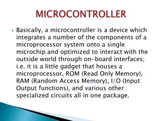
8051 Architecture. Microcontroller ( dkt 225). Explain the 8051 hardware architecture List and explain the main 8051 pins and their functions Describe the 8051 software architecture Draw the 8051 block diagram Illustrate the 8051 memory organization

E N D
8051 Architecture Microcontroller (dkt 225)
Explain the 8051 hardware architecture • List and explain the main 8051 pins and their functions • Describe the 8051 software architecture • Draw the 8051 block diagram • Illustrate the 8051 memory organization • List and explain SFRs and their functions Learning outcomes
Programmer’s View • Memory Organization • Register Set • Instruction Set • Hardware Designer’s View • Pin-out • Timing characteristics • Current / Voltage requirements 8051 architecture
8051 Pins & Functions I/O Port Internal I/O Pin Configuration I/O Pin Current Limitations HARDWARE architecture
8051 pins & FUNCTIONS I/O port – interfacing to external devices Master reset for 8051. Dual purpose : 1.general purpose I/O 2.special features On-chip oscillator inputs. Need to be driven by a crystal frequency 12MHz Output 0V
8051 PINS & FUNCTIONS Input +5V General purpose I/O port External Access. Address latch enable. Uses for demultiplexing the address and data bus. Program store enable. Output signal. Usually connect to EPROM Dual purpose : 1. general purpose I/O. 2. as the high byte of the address bus for designs with external code memory or more than 256 bytes of external memory
Consist of 4, 8 bits IO ports (32 IO pins) • PORT0 – P0 • PORT1 – P1 • PORT2 – P2 • PORT3 – P3 • These ports can be configured as input or output by setting appropriate IO register • 0 – set IO pin as output • 1 – set IO pin as input 8051 PINS & FUNCTIONS – IO PORTS
This is a simplified overview of what is connected to a pin inside the microcontroller. It concerns all pins except those included in P0 which do not have embedded pull up resistor. 8051 PINS & FUNCTIONS – IO PORTS • INTERNAL IO PIN CONFIGURATION Input/Output Pin
8051 PINS & FUNCTIONS – IO PORTS • INTERNAL IO PIN CONFIGURATION Output Pin • Setting pin as output : • Write ‘0’ to a bit of Port register • Internal latch to turn on the FE transistor. • The appropriate pin is directly connected to ground.
Setting pin as input : • Write ‘1’ to a bit of Port register • Output FE transistor to turn off. • Appropriate pin remains connected to voltage power supply through a pull-up resistor of high resistance. 8051 PINS & FUNCTIONS – IO PORTS • INTERNAL IO PIN CONFIGURATION Input Pin
Setting pin as output • Write 0 – the pin will connected to ground • Cause the pin become ‘open drain’ • Setting pin as input • Write 1 – the pin will float • Has unlimited input resistance • Has no voltage coming from ‘inside’ • Therefore, it necessary to connect the external pull up resistor to use this pin as a simple IO pin 8051 PINS & FUNCTIONS – IO PORTS • INTERNAL IO PIN CONFIGURATION – PORT 0
When configured as outputs ( logic zero (0) ), single port pins can "receive" current of 10mA. • If all 8 bits on a port are active, total current must be limited to 15mA (port P0: 26mA). • If all ports (32 bits) are active, total maximal current must be limited to 71mA. • When configured as inputs (logic 1), embedded pull-up resistor provides very weak current, but strong enough to activate up to 4 TTL inputs from LS series. 8051 PINS & FUNCTIONS – IO PORTS • IO PIN CURRENT LIMITATIONS
Basic 8051 block diagram Memory organization Special Function Register (SFR) Software architecture
monitors and controls all operations being performed within the microcontroller • It consists of several smaller units • Instruction decoder - a part of electronics which recognizes program instructions and on the basis of which runs other circuits. • Arithmetical Logical Unit (ALU) - performs all mathematical and logical operations with data. • Accumulator - is a special type of the SFR closely related to operating mode of the ALU Central processing unit (CPU)
Program Memory (ROM) • permanently stores a program being executed • Data Memory (RAM) • used for temporary storing and keeping different data and constants created and used during operating process • Memory is erase when power loss • EEPROM • a special type of memory which not all the types of the microcontrollers have. • content can be changed during program execution (similar to RAM ), but it is permanently saved even after the power goes off (similar to ROM) • used for storing different values created and used during operating process and which must be saved upon turning off the device memory
16 bit register The value is 0000h after Reset or POR An engine which start the program Indicates the address in memory where next instruction to execute is found Immediately after its execution, the value of the counter is incremented by 1 Program counter
Timer • Act as stopwatch inside microcontroller • Normally used to provide program delay • Counter • Similar to timer but used external pulse to operate • WatchDog Timer • is a timer connected to a particular and totally independent RC oscillator within the microcontroller. • Used to reset the microprocessor and start the program from beginning Timer/counter
SFRs (Special Function Registers) • control some of interfaces within the microcontroller • Input/Output Ports (IO Ports) • Used by microcontroller to interface with other devices • Oscillator (OSC) - Clock • Provide pulses to enable harmonious and synchronic operating of all other parts of the microcontroller others
Divided into two • Program Memory (ROM, FLASH) • Used to store permanently the executed program • Can be built in the microcontroller or added from outside as a separate chip • Size ranges from 512B to 64KB • Data Memory (RAM) • Used for temporary storing and keeping immediate results and variable • The content of this memory is erased once the power is off • Small size (up to few KB) Memory organization • - Separate address spaces for program and data memory -
Program memory can only be read. Can be up to 64k bytes of program memory The lowest 4k bytes on-chip, the rest external The read strobe for external program memory is PSEN (Program Store Enable) Oldest model of 8051 family (such as 803x series) do not have internal program memory. PROgram memory
After reset, the MCS-51 starts fetching instructions from 0000H. • This can be either on-chip or external depending on the value of the EA* input pin. • If EA* is low, then the program memory is external. • If EA* is high, then addresses from 0000H to 0FFFH will refer to on-chip memory and addresses 1000H up to FFFFH refer to external memory. • Note that the 8031 must have its EA* connected low as all of its memory is external. PROgram memory
Port 0 acts as a multiplexed address/data bus. Sending the low byte of the program counter (PCL) as an address. Port 2 sends the program counter high byte (PCH) directly to the external memory. The signal ALE operates as in the 8051 to allow an external latch to store the PCL byte while the multiplexed bus is made ready to receive the code byte from the external memory. Port 0 then switches function and becomes the data bus receiving the byte from memory. PROgram memory • ACCESS TO EXTERNAL MEMORY
PROgram memory • ACCESS TO EXTERNAL MEMORY
The 8051 has 256 bytes of RAM on-chip. • The lower 128 bytes are intended for internal data storage. • The upper 128 bytes are the Special Function Registers (SFR). • The lower 128 bytes are not to be used as standard RAM. • They house the 8051’s registers, its default stack area, and other features. Data memory FFH Special Function Registers 80H 7FH Internal Data Storage 00H Note : Internal Data Memory address always one byte wide
DATA memory Upper 128 byte of internal RAM Lower 128 byte of internal RAM
The lowest 32 bytes of the on-chip RAM form 4 banks of 8 registers each. • Only one of these banks can be active at any time. • Bank is chosen by setting 2 bits in PSW (Program Status Word) • Default bank (at power up) is bank 0 (locations 00 – 07). • The 8 registers in any active bank are referred to as R0 through R7 • Given that each register has a specific address, it can be accessed directly using that address even if its bank is not the active one Data memory – lower 128 byte
The next 16 bytes – locations 20H to 2FH – form a block that can be addressed as either bytes or individual bits. • The bytes have addresses 20H to 2FH. • The bits have addresses 00H to 7FH. • Specific instructions are used for accessing the bits. • Locations 30H to 7FH are general purpose RAM. Data memory – lower 128 byte
Data memory – lower 128 byte Bit addressable memory locations
The upper 128 bytes of the on-chip RAM are used to house Special Function Registers (SFR) • In reality, only about 25 of these bytes are actually used. The others are reserved for future versions of the 8051. • These are registers associated with important functions in the operation of the MCS-51. • Some of these registers are bit-addressable as well as byte-addressable. • The address of bit 0 of the register will be the same as the address of the register. Data memory – upper 128 byte
Data memory – upper 128 byte 8051 SFR Memory Map Not all of the addresses are occupied Bit/Byte addressable registers Byte only addressable registers
SFR are used by microcontroller as control table for running and monitoring microcontroller’s operations. • Each of this registers and each bit they include, has • Name • Address in scope of RAM • Clearly define purpose Data memory – Special Function register
ACC : Accumulator and B registers – 8 bit each DPTR : Data Pointer [DPH:DPL] – 16 bit combined Stack pointer SP – 8 bit PSW : Program Status Word Port Latches Serial Data Buffer Timer Registers Control Registers Data memory – Special Function register
General purpose register. • Serves for storing immediate results during operation. • Commonly used for move and arithmetic instructions. • Most of the move instruction must go through accumulator • The results of arithmetical operation is placed into accumulator • Can be referred to in several ways: • Implicitly in opcodes. • Referred to as ACC (or A) for instructions that allow specifying a register. • By its SFR address 0E0H. • Bit addressable. • ACC.2 means bit 2 of the ACC register. Accumulator (acc)
Used during multiply and divides operation • mul AB, div AB (used by two opcodes) • B register holds the second operand and will hold part of the result • Upper 8 bits of the multiplication result • Remainder in case of division. • Can be used as a temporary register (as spare Accumulator) • Can also be accessed through its SFR address of 0F0H. • Bit addressable. B register
Two 8-bit registers that can be combined into a 16-bit DPTR – Data Pointer. • Used by commands that access external memory • Also used for storing 16bit values mov DPTR, #data16 ; setup DPTR with 16bit ext address movx A, @DPTR ; copy mem[DPTR] to A • Can be accessed as 2 separate 8-bit registers if needed. • DPTR is useful for string operations and look up table (LUT) operations. Dpl and dph register
SP is the stack pointer. • SP points to the last used location of the stack. • Push operation will first increment SP and then copy data. • Pop operation will first copy data and then decrement SP. • In 8051, stack grows upwards (from low memory to high memory) and can be in the internal RAM only. • On power-up, SP points to 07H. • Register banks 2,3,4 (08H to 1FH) form the default stack area. • Stack can be relocated by setting SP to the upper memory area in 30H to 7FH (General Purpose RAM) • mov SP, #32H Sp (stack pointer) register
Contains several status bits that reflect the current state of the CPU Program Status Word is a “bit addressable” 8-bit register. psw (program status word) register
P – Parity bit • 1 – if the accumulator contains odd number of ‘1’ • 0 – if the accumulator contains even number of ‘1’ • OV – Overflow • 1 – if the results of arithmetic operation is greater than 255 (decimal) • 0 – no overflow • Used to detect errors in signed arithmetic operation • RSO, RSI – Register Bank Select Bit • Used to select one of the four register banks in RAM psw (program status word) register
F0 – Flag 0 • General purpose flag bit available to the user • AC – Auxiliary Carry • 1 – if there is a carry fromD3 to D4 during an ADD or SUB operation • 0 – otherwise • Used for BCD operation • CY– Carry • 1 – when there is a carry out from the D7 bit or there is a borrow into the D7 bit • 0 – otherwise psw (program status word) register
Specify the value to be output on the specific output port or the value read from the specific input port. • Bit addressable. • First bit has the same address as the register. • Example: P1 has address 90H in the SFR, so • P1.7 or 97H refer to the same bit • Bit configuration • 0 – set pin as output • 1 – set pin as input Port latches (p0,p1,p2,p3) register