Download
1 / 24
240 likes | 370 Views
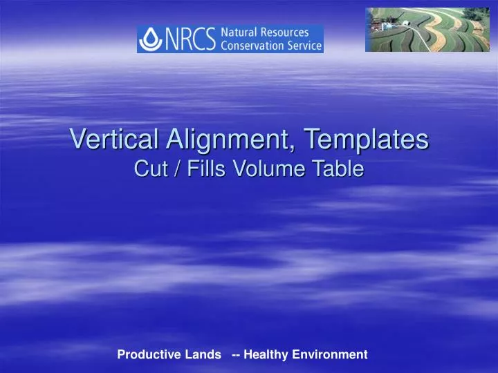
Vertical Alignment, Templates Cut / Fills Volume Table. Productive Lands -- Healthy Environment. Agenda Items. Horizontal Alignments Profiles Vertical Alignments Templates Profiles in Paper Space. Once you have your surface done and you have your contours lines.

E N D
Vertical Alignment, Templates Cut / Fills Volume Table Productive Lands -- Healthy Environment
Agenda Items • Horizontal Alignments • Profiles • Vertical Alignments • Templates • Profiles in Paper Space
Once you have your surface done and you have your contours lines. • Draw a Polyline where your CL is going to be from node to node starting at the upstream station.
Civil Design – Alignments - Define from polyline Pick your Pline Civil Design – Alignments - Station Label Settings Note: Make sure the first three boxes are checked, you can also check ‘Perpendicular labels” ; “Station read along road” and “Plus sign location” if you want, this will only change the appearance.
Civil Design – Alignments - Create Station Labels If text is too small or too large, “rescale” it through; Utilities – Rescale - Block/text
Civil design – Profile - Profile Settings - Values Civil design – Profile - Existing Ground - Sample From Surface
You will get a message **If you do not get this message you might have to start over** Civil design – Profile - Create Profile - Full Profile
Civil design - Profile - FG Centerline Tangents - Create Tangents Vertical Alignment
It will ask you to pick your profile and everything will disappear. Pick your Vertical Alignment. Hit enter and everything will show up again. Civil design – Profile - FG Vertical Alignment – Define FG Centerline Civil design – Profile - FG Vertical Alignment - Import Your grades, PVI’s (Point of Vertical Inflection) and their elevations will now be labeled.
Click ok Click enter for all the values, enter a critical station you might want, You will get a message that “You have sampled sections for 2207.8720 feet of alignment”. Civil Design - Cross Sections - Existing Ground - Sample from Surface Civil Design - Cross Sections - View/Edit Sections After this you can plot the sections. Follow set of instructions attached.
CL A B 10’ Fig. 1 Template of 20’ waterway Template for Waterways Civil Design - Cross Sections - Draw Template • Command Line • Starting Point – Point A on Fig 1 • Select Point (Relative/Grade/Slope/Close/Undo/eXit) We’re selecting R • Change in Offset (Grade/Slope/Close/Points/Undo/eXit) For our 20’ waterway template, type “-10”. Note: Be aware of the minus sign • Change in elevation - Type “0” • Type “C” for Close
CL A B 10’ Fig. 1 Template of 20’ waterway • Command Line • Pick finish Ground reference Point - That would be the point attached to the center line of your profile, that would be point A in Fig. 1 Using osnaps, pick point A • Is Template Symmetrical - Default “Yes” • Select Objects - Pick your horizontal template line. Civil Design - Cross Sections – Templates - Define Template • You’ll get to the Surface Materials Names - Click ok • Pick Connection point out – This will be point B in Fig. 1 • Pick Datum points (left to Right) - Pick first point B and then point A • Hit “Enter” • Save Template – Default “Yes” - “20’ww” • Define another template (Yes/No) Type N and “Enter” • When you import the template, it will be applied to your finished ground profile at the grades you designed.
Civil Design - Cross Sections - Design Control - Edit Design Control
Command Line • Import Catch Points (Y/N) – Type N “This will put actual datum points representing daylight lines on your drawing. • Import daylight line (Y/N) – enter default “Yes” Civil Design - Cross Sections - Point Output – Catch Points To DWG
Command Line • Volume Computation Type (Prismoidal/Avgendarea) – Enter default “Avgendarea” • Use of Curve Correction (Y/N) Enter default “Yes” • Leave the cut/fill adjustment factors at <1.00>. Pick an insertion point off your work space. Civil Design - Cross Sections - Total Volume Output -Volume Table This will show up on your screen. Congrats!
In our profile paper we will have a 2.5” by 2.5” main grid. We have to accommodate our profile length and height in this grid. In our example it will be 2000 ft. of length and almost 50 ft. of height. We will say 2000 ft. divided by 5 main grid spaces equals 400 ft. Since each 2.5 by 2.5 square is divided into ten vertical strips, we will say that 1” = 160 ft. This is our horizontal scale. Now, for the vertical part is the same, we have 50 ft. in three main grid spaces. That will lead us to use each square equals 20 ft. And since each square is divided also into ten horizontal strips, we will say that 1” = 8 ft. This is our vertical scale.
Now, we go back to model space and go to Project – Drawing Set up – Scale – Horizontal – Custom and type 160.0. We could change also the vertical scale here, but for this example we won’t. Also, if you go to Format – Text Style – Height – Type “your horizontal scale multiplied by the standard text height 0.0781” When the Profile Generator prompts, we will change four things. The Datum, we will change it to something close to the minimum. Also here is where we are going to change the vertical scale to 8.0 Horizontal spacing will be whatever number you came up for the horizontal main grid divided by 10. And the vertical spacing will be 1.