Download
1 / 66
660 likes | 779 Views
Fluvial Processes “the great sculptor of the landscape”. I. The River Channel A. Basic Mechanics 1. Laminar Flow 2. Turbulent Flow. I. The River Channel A. Basic Mechanics 1. Laminar Flow 2. Turbulent Flow 3. Reynolds Number

E N D
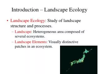
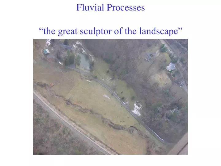
Fluvial Processes “the great sculptor of the landscape”
I. The River Channel A. Basic Mechanics 1. Laminar Flow 2. Turbulent Flow
I. The River Channel A. Basic Mechanics 1. Laminar Flow 2. Turbulent Flow 3. Reynolds Number Re = driving forces = V D p = (velocity * depth * fluid density) resisting forces u (fluid viscosity) laminar < 500 700 < turbulent \
I. The River Channel B. Flow Equations and Resisting Forces Discharge = velocity * depth * width Q = V*A 1. Manning Equation
1.Manning Equation v = R 2/3 S ½ n Where v = average flow velocity r = hydraulic radius s = channel slope (unitless) n = Manning roughness coefficient R = A/P A = Area P = Wetted Perimeter
Q = A R 2/3 S ½ N Where Q = average flow discharge A = area of channel R = hydraulic radius S = channel slope (unitless) n = Manning roughness coefficient R = A/P A = Area P = Wetted Perimeter
I. The River Channel B. Flow Equations and Resisting Forces 1. Manning Equation 2. Chezy Equation V = C *(RS)1/2
II. Sediment in Channels A. Transportation 1. Suspended load 2. Bedload B. Entrainment and Erosion
II. Sediment in Channels A. Transportation 1. Suspended load 2. Bedload 3. Washload B. Entrainment and Erosion C. Deposition
II. Sediment in Channels A. Transportation 1. Suspended load 2. Bedload 3. Washload B. Entrainment and Erosion C. Deposition “ a battle between velocity and gravity”
III. The Quasi-Equilibrium Condition A. Hydraulic Geometry
III. The Quasi-Equilibrium Condition A. Hydraulic Geometry Q = V*A
III. The Quasi-Equilibrium Condition A. Hydraulic Geometry Q = V*A Q = V * w * d
III. The Quasi-Equilibrium Condition A. Hydraulic Geometry Q = V*A Q = V * w * d w = aQb d = cQ f v = kQ m
M = 0.26 A. Hydraulic Geometry M = 0.4 “at a station trends” M = 0.34
M = 0.5 A. Hydraulic Geometry M = 0.4 “distance downstream trends” M = 0.1
B. The Influence of Slope Slope (ft/mi)
III. The Quasi-Equilibrium Condition C. Channel Shape ….in cross section: F = 255M-1.08 Where F = width to depth ratio (W/D) M = % silt and clay in channel
IV. Channel Patterns ….in plan view (bird’s eye) Straight Meandering Braided Transition between Straight And Meandering is when Sinuosity is 1.5
IV. Channel Patterns From: Montgomery and Buffington, 1997
(pools and riffles) Riffles are spaced ~ 5-7 times the channel width
` (pools and riffles)
IV. Channel Patterns Meanders…….
IV. Channel Patterns Meanders…….
IV. Channel Patterns Meanders…….
IV. Channel Patterns Meanders…….
A few final words on stream form…. Anastomosing channels braided
A few final words on stream form…. The factors responsible are……
A few final words on stream form…. Why do channels take on a certain pattern?????
A few final words on stream form…. Why do channels take on a certain pattern????? It’s primarily due to the relationship between slope and discharge (or velocity)
A few final words on stream form…. Why do channels take on a certain pattern????? It’s primarily due to the relationship between slope and discharge (or velocity) The ole’ Chezy Equ: V = C *(RS)1/2 or V = C *(DS)1/2
A few final words on stream form…. It’s primarily due to the relationship between slope and discharge (or velocity) The ole Chezy Equ: V = C *(DS)1/2 V = velocity C = roughness D = depth of flow S = slope of channel
V = C *(DS)1/2 V = velocity C = roughness D = depth of flow S = slope of channel The change in slope is a RESPONSE to changes in channel shape, NOT a cause of braiding Increasing the slope of a stream DOES NOT cause it to braid.
V. Rivers, Equilibrium, and Time “the profile of streams”