Download
1 / 1
10 likes | 297 Views
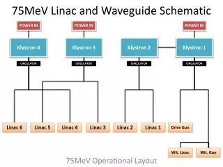
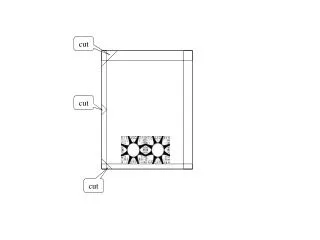
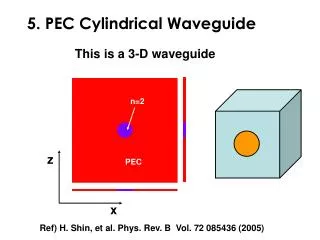
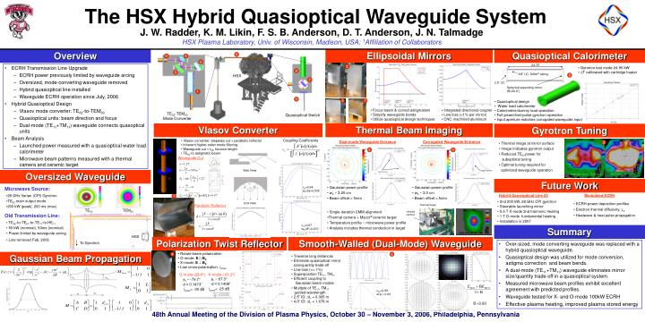
24.75”. 3/8” I.D. Teflon ® tubing. 8. 2.5” I.D. . Spherical expanding mirror (R=20.0”). Side View. c ab =0.99 w/a = 0.64. c a =0.94 w 0 /2a=0.505. B =0.83. End View. HSX. c a =0.97 w 0 /4F=0.470. To Gyrotron. Optimal Tuning. The HSX Hybrid Quasioptical Waveguide System.

E N D
24.75” 3/8” I.D. Teflon® tubing 8 2.5” I.D. Spherical expanding mirror (R=20.0”) Side View cab=0.99 w/a = 0.64 ca=0.94 w0/2a=0.505 B =0.83 End View HSX ca=0.97 w0/4F=0.470 To Gyrotron Optimal Tuning The HSX Hybrid Quasioptical Waveguide System J. W. Radder, K. M. Likin, F. S. B. Anderson, D. T. Anderson, J. N. Talmadge HSX Plasma Laboratory, Univ. of Wisconsin, Madison, USA; 1Affiliation of Collaborators Overview Ellipsoidal Mirrors Quasioptical Calorimeter 6 5 4 2 • ECRH Transmission Line Upgrade • ECRH power previously limited by waveguide arcing • Oversized, mode-converting waveguide removed • Hybrid quasioptical line installed • Waveguide ECRH operation since July, 2006 • Hybrid Quasioptical Design • Vlasov mode converter: TE02-to-TEM00 • Quasioptical units: beam direction and focus • Dual-mode (TE11+TM11) waveguide connects quasoptical units • Beam Analysis • Launched power measured with a quasioptical water load calorimeter • Microwave beam patterns measured with a thermal camera and ceramic target 2 • Gyrotron test mode 24-96 kW • DT calibrated with cartridge heater 8 3 HSX 7 1 9 3 7 • Quasioptical design • Water load calorimeter • Calorimeter/dummy load operation • Full-power/test-pulse gyrotron operation • Input aperture matches corrugated waveguide input • Focus beam & correct astigmatism • Simplify waveguide bends • Utilize quasioptical design techniques • Integrated directional coupler • Low loss (<1% per mirror) • CNC machined aluminum TE02-TEM00 Mode Converter Quasioptical Switch Vlasov Converter Thermal Beam Imaging Gyrotron Tuning Coupling Coefficients • Vlasov converter: stepwise cut + parabolic reflector • Inherent higher-order mode filtering • Waveguide cut = LB, bounce length • TE02-to astigmatic beam Dual-mode Waveguide Entrance Corrugated Waveguide Entrance • Thermal image at mirror surface • Image indicates gyrotron output • Reduced TE02 power for • suboptimal tuning • Optimal tuning required for • optimized waveguide operation 2 5 9 Waveguide Cut Target marker Oversized Waveguide Target markers Suboptimal Tuning Future Work • Gaussian power profile • w0 ~ 2.0 cm • Beam offset < 5mm Microwave Source: d • Gaussian power profile • w0 ~ 3.25 cm • Beam offset < 5mm Hybrid Qausioptical Line #2 Modulated ECRH • 28 GHz Varian (CPI) Gyrotron • TE02 main output mode • 200 kW (peak), 200 ms (max) 1 • 2nd 200 kW, 28 GHz CPI gyrotron • Steerable launching mirror • 0.5 T X-mode 2nd harmonic heating • 1 T O-mode fundamental heating • Installation in 2007 • ECRH power deposition profiles • Electron thermal diffusivity, e • Heatwave & heat pulse propagation Thermal target Parabolic Reflector TE02 TEM00 • Single-iteration CMM alignment • Thermal camera + Macor® ceramic target • Temperature profile ~ microwave power profile • Analysis includes thermal conduction in target Infrared camera Old Transmission Line: • TE02-to-TE01-to-TE11-to-HE11 • 50 kW (nominal), 50ms (nominal) • Power limited by waveguide arcing • Line removed Feb, 2006 Summary Polarization Twist Reflector Smooth-Walled (Dual-Mode) Waveguide • Over-sized, mode converting waveguide was replaced with a hybrid quasioptical waveguide. • Quasioptical design was utilized for mode conversion, astigma correction and beam bends. • A dual-mode (TE11+TM11) waveguide eliminates mirror size/quantity trade-off in a quasioptical system. • Measured microwave beam profiles exhibit excellent agreement with predicted profiles. • Waveguide tested for X- and O-mode 100kW ECRH • Effective plasma heating, improved plasma stored energy • Rotate beam polarization • O-mode: E || B0 • X-mode: E^ B0 • Low cross-polarization, icross Gaussian Beam Propagation 4 6 • Traverse long distances • Eliminate quasioptical mirror • size/quantity trade-off • Low loss (<< 1%) • Superposition TE11, TM11 • Efficient coupling to Gaussian beam modes • O-mode (28.8º) • 1 = -79.7° • d = 0.1473” • icross< -30 dB • X-mode (-61.2º) • 1 = 67.3° • d = 0.1408” • icross< -25 dB • Multiple of TE11, TM11 guided wavelength • 2.5” ID: L = 0.065 m • 4.0” ID: L = 1.676 m ” ” ” ” ”