Download
1 / 19
190 likes | 194 Views
Learn about trusses, their design principles, and how to analyze and size truss members using the method of joints and sections. Also, use the provided forces for calculations.

E N D
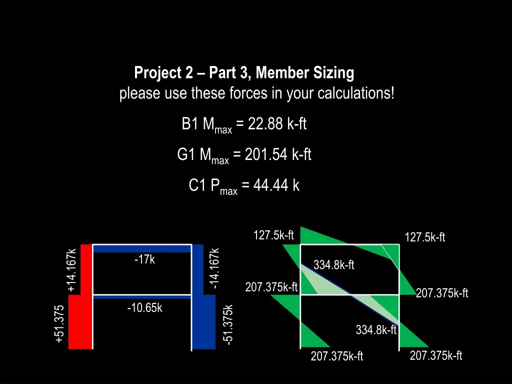
Project 2 – Part 3, Member Sizingplease use these forces in your calculations! B1 Mmax = 22.88 k-ft G1 Mmax = 201.54 k-ft C1 Pmax = 44.44 k 127.5k-ft 127.5k-ft -17k 334.8k-ft -14.167k +14.167k 207.375k-ft 207.375k-ft -10.65k +51.375 -51.375k 334.8k-ft 207.375k-ft 207.375k-ft
A truss is: • A lightweight frame used for relatively long spans • composed primarily of triangles, an inherently stable and non-deformable geometry • a flexible structure which withstands dynamic loads well
When would one use a truss? Aesthetics? Structural capability? Architectural transparency?
Rules for trusses: 1. All members are straight.
Rules for trusses: 2. Members are pin-jointed at all connections.
Rules for trusses: 3. External loads and reactions occur at joints only.
Rules for trusses: 4. Axes of all members align to a single point at joints.
Truss members following these rules can resist only axial forces: TENSION Trusses have a very efficient load path, as no members are in bending. COMPRESSION
In Project 1 you qualitatively analyzed 3-dimensional trusses. Doing a quantitative analysis in 3-D can be quite complicated, so we will stick to 2-D “flat” trusses. After all, many truss systems are largely 2-dimentional, or consist of many 2-D plane trusses parallel to each other.
“Analyze” a truss = to determine whether each member is in tension or compression, and with what magnitude, for a given loading condition. The big picture: a truss is a composite spanning member, like a solid beam but made of many smaller parts to maximize material efficiency. Truss: Solid beam: P P C C C C C C C T T T T T T
Truss: Solid beam: C C C C C C C T T T T T T C C C C P C C C C T T V V V T T Ry1 Ry2 C C T T V V C C T T
Method of Joints: • Draw free-body diagram of overall truss. • Determine reactions at supports, using SFx = 0, SFy = 0, SMany = 0. • Draw the free body diagram for each joint, one at a time. • Use SFx = 0, SFy = 0 at each joint to solve for member forces. • Go to an adjacent or neighboring joint and repeat. • Summarize all member forces in a diagram of the whole truss.
Method of Sections: • Draw free-body diagram of overall truss. • Determine reactions at supports, using SFx = 0, SFy = 0, SMany = 0. • Make a cut through the truss that goes through the member(s) in question and draw this new partial free body diagram. • Use SFx = 0, SFy = 0, SMany = 0 for this partial truss to solve for member forces.
Project 2 – Part 3, Member Sizingplease use these forces in your calculations! B1 Mmax = 22.88 k-ft G1 Mmax = 201.54 k-ft C1 Pmax = 44.44 k 127.5k-ft 127.5k-ft -17k 334.8k-ft -14.167k +14.167k 207.375k-ft 207.375k-ft -10.65k +51.375 -51.375k 334.8k-ft 207.375k-ft 207.375k-ft