Download
1 / 11
160 likes | 434 Views
ELECTRICAL SYSTEM The helicopter is equipped with a 28 VDC electrical system. Power for this system is obtained from a nickelcadmium 24 volt, 17 ampere-hour battery and a 30 volt, 200 ampere starter-generator.

E N D
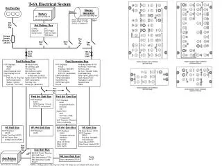
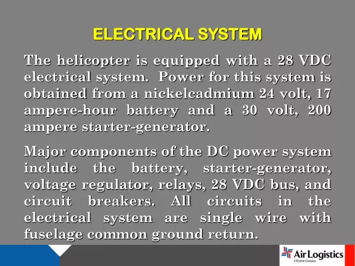
ELECTRICAL SYSTEM The helicopter is equipped with a 28 VDC electrical system. Power for this system is obtained from a nickelcadmium 24 volt, 17 ampere-hour battery and a 30 volt, 200 ampere starter-generator. Major components of the DC power system include the battery, starter-generator, voltage regulator, relays, 28 VDC bus, and circuit breakers. All circuits in the electrical system are single wire with fuselage common ground return.
The negative terminals of the starter-generator and the battery are grounded to the helicopter structure. Controls for the electrical system are located on the overhead console and instrument panel. The generator is provided with over voltage protection set at 31 + 1 volts. Upon exceeding this limit, the voltage regulator will disconnect the starter-generator from the system. The failure of the generator can be determined by the GEN FAIL caution light and a zero loadmeter reading. The battery can supply emergency DC load for approximately 1 hour with a 17 ampere drain.
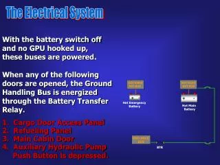
The BATTERY switch may be placed in the ON position after external power is applied. In the ON position, battery charging is supplied by external power and must be monitored. In the event the BATTERY HOT warning light illuminates, the BATTERY switch shall be turned OFF. If the Battery switch is turned OFF, and the BATTERY RLY caution light illuminates, this indicates that the battery relay has failed to open. If the battery relay fails to open, the battery will continue to receive a charge from the generator. To prevent this, the pilot should turn GEN switch OFF.
The battery will continue to run all electrical systems through the closed battery relay. To reduce the load on the overheated battery, the pilot should pull the circuit breakers on all nonessential systems. The LEFT BOOST circuit breaker should be left in to ensure that fuel transfer from front tanks to main tank continues. External power may be supplied to the helicopter by means of a receptacle located on the lower front section of the helicopter. An auxiliary power unit capable of delivering 28 VDC with a 500 ampere rating is required.
AUDIO WARNING SYSTEM The ROTOR LOW RPM and ENG OUT audio warnings are emitted from cabin horns located aft and to the left of the overhead console. The muting button for the system is located on upper right side of instrument panel, and mutes warning system audio. The rotor RPM audio warning activates (simultaneously with ROTOR LOW RPM caution light illumination) whenever the ROTOR decays below 90% RPM. The rotor RPM audio will produce a steady sound until the Rotor increases above 90% RPM.
Helicopters equipped with a WRN HORN MUTE system will produce a steady sound when the ROTOR decays below 90% RPM, regardless of collective position. The engine out audio warning (if functional) is activated (simultaneously with ENG OUT warning light illumination) when the GAS PRODUCER drops below 55 + 3% RPM. The engine out audio will produce an intermittent sound until the GAS PRODUCER increases above 55% RPM.
BATTERY RELAY EXT. POWER RELAY BATTERY BATTERY SWITCH EXTERNAL POWER RECEPTACLE LOAD METER 28 VDC BUS STARTER GENERATOR LINE CONTROL RELAY STARTER SWITCH STARTER RELAY GENERATOR RESET SWITCH VOLTAGE REGULATOR
ELECTRICAL QUESTIONS?