Download
1 / 49
490 likes | 590 Views
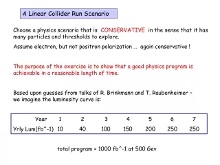
The High Energy Potential of a Linear Collider. R. D. Ruth Stanford Linear Accelerator Center. Outline. Introduction Luminosity Low emittance generation and preservation Final Focus and Beam Beam Energy High Gradient PowerTransformation (RF Power). Introduction.

E N D
The High Energy Potential of a Linear Collider R. D. Ruth Stanford Linear Accelerator Center R. D. Ruth, LineDrive, May 2001
Outline • Introduction • Luminosity • Low emittance generation and preservation • Final Focus and Beam Beam • Energy • High Gradient • PowerTransformation (RF Power) R. D. Ruth, LineDrive, May 2001
Introduction • Goal: Physics at the Energy Frontier • Electron positron circular colliders: • Several generations of storage rings • Factor of 100 in energy • Each generation has been the parent/teacher of the next. • Have moved onto the Luminosity/Factory frontier: precision physics. • Electron positron Linear Colliders • We have the SLC as the parent at 100 GeV. • We have proposals for linear colliders at ½ to 1 TeV. • Can we build on this basis to provide a future reach to multi TeV energy? R. D. Ruth, LineDrive, May 2001
Luminosity • The largest jump for all approaches to linear colliders is the luminosity. • Future designs build on the hard won success of the SLC. • Low-emittance (high-brightness) beam generation • SLC had the first damping rings based circular storage rings. • KEK ATF is the successful prototype for NLC/JLC for ½ to 1 TeV. • This success is based on experience with similar storage rings and light sources. • Multi TeV colliders plan for even smaller emittance to achieve higher luminosity necessary to do physics at high energy. • These must build on the experience gained in the KEK ATF and the next generation damping rings. R. D. Ruth, LineDrive, May 2001
Luminosity continued • Preservation of low-emittance beams • SLC first tests of ‘BNS’ damping (became routine). • SLC applied beam-based compensation envisioned for NLC (became routine). • SLC provided parameter sensitivity for NLC designs (low charge single bunches). NLC less sensitive in a scaled sense than SLC. • SLC showed the critical importance of good diagnostics, if a dilution could be measured and was stable, it could be compensated. • Moved correction techniques from traditional trajectory or first moment correction, to emittance or second moment correction. • Detailed simulations done world wide together with SLC experience have given us confidence that the next generation of linear colliders will be able to preserve the tiny beams to the final focus. • Multi TeV linear colliders will necessarily be based on the next round of learning from the ½ to 1 TeV machine. R. D. Ruth, LineDrive, May 2001
Luminosity continued • Final focus, small spots, flat beams, beam-beam effects • SLC luminosity increases came from preserving low emittance flat beams and focusing them to a spot size smaller than the design! • SLC showed the importance of collimation, tuning and feedback for stable running, not only trajectory, but also beam size. • FFTB, the next generation prototype, showed more demagnification than required for the NLC, (spot size tuning required.) • The NLC final focus is a simpler, new generation version upgradeable to multi TeV. • Multi TeV colliders will need the experience of crossing angles, bunch trains, beam-beam generated photons and pairs, background handling from the ½ to 1 TeV generation. R. D. Ruth, LineDrive, May 2001
Luminosity • Summary • There is a strong experimental base for the projected luminosity for ½ to 1 TeV. • A key feature is that we must pay attention to the interaction of the trajectory and emittance or beam size. • Feedback, beam-based alignment, special steering techniques for low emittance, stable precise instrumentation are all required. • The highest luminosity will take time to obtain as we learn to use the next generation linear collider. • We must have the experience of using a ½ to 1 TeV linear collider before we could move on to a multi TeV linear collider. R. D. Ruth, LineDrive, May 2001
Energy • All linear accelerators act like transformers • Power from the Grid ( or co-generation plant) is transformed to a high-energy, pulsed, low-current electron/positron beam. • Multi TeV linear colliders require high-gradient acceleration. • The Acceleration gradient sets the length scale, much like superconducting magnet field sets the length scale for LHC. • Power must be compressed and converted to RF to accelerate the beam. • This is done by the combination of modulators, klystrons and RF pulse compression for conventional systems. • Two-Beam RF power generation is envisioned for Multi TeV linear colliders because it provides a frequency independent energy compression. It can provide power at frequencies where there are no other sources. R. D. Ruth, LineDrive, May 2001
High Gradient Acceleration • Historically, there has been and is hope that higher frequency RF systems can intrinsically support higher gradients. • The NLC and higher frequency designs have been based on this and early experimental results that showed high gradients in short structures which required relatively low power. • Recent results with long structures driven by high power RF have shown that there is a different dimension to the problem that is critical. R. D. Ruth, LineDrive, May 2001
High Gradient Data • S-band • 3m Long (low vg) traveling wave ~ 20-30 MV/m • 1m short (lower vg) traveling wave ~ 60 MV/m • Single cell standing wave ~100 MV/m • X-band • 2m long (high vg) traveling wave ~ 40-50 MV/m • 0.3m short (low vg) traveling wave ~ 120 MV/m • Single cell standing wave ~ 200 MV/m R. D. Ruth, LineDrive, May 2001
Experimental Observations • The initiation of ‘conditioning’ begins at higher field with lower group velocity structures. • In a breakdown event in a traveling wave structure, in many cases a large fraction of the RF energy is dumped in the structure. • The long, high group velocity structures have shown damage sufficient to effect the RF properties. • Historically, the highest gradients obtained have occurred in very short low group velocity structures or standing wave structures. R. D. Ruth, LineDrive, May 2001
Some more observations • In matched traveling wave structures • Almost all the transmission of RF is blocked • Evidence of acceleration of electrons (x rays). • Evidence of excited copper atoms (light) and CO (RGA). • A large fraction of the RF energy is typically absorbed inside the structure. • The remainder is reflected back. • Turn-on time ~ 20 nsec. R. D. Ruth, LineDrive, May 2001
High Gradient Damage • Damage (pitting) around irises is observed in the front of the structure (1000 hours @ ~ 50 MV/m) • The downstream part is undamaged ( same surface field !) C. Adolphsen R. D. Ruth, LineDrive, May 2001
Low Group Velocity Structure DS2S: Last 52 Cells of a 206 cell 1.8 m long structure run for >1000 hrs at NLCTA Group Velocity Varies from 5% to 3% c Processed > 1500 hours @50-70 Mv/m No damage seen after initial processing duringfirst 250 hours Average Gradient (MV/m) Switched from 50 ns to 250 ns Pulse Length C. Adolphsen Time with RF On at 60 Hz (hours) R. D. Ruth, LineDrive, May 2001
Low Group Velocity Structures • Tested two additional structures with 5% group velocity like DS2S structure - performed like DS2S • Rapid processing to 60 MV/m • Ran between 65 and 75 MV/m for 500 hours before being removed to test other potentially higher gradient structures Trip rate per hour Processing history Gradient (MV/m) R. D. Ruth, LineDrive, May 2001 Gradient (MV/m) Time (hours)
Prospects for High Gradient in Traveling Wave Structures. • Tests are ongoing on even lower group velocity structures for NLC. • This research effort is in the midst of a breakthrough in understanding and development. • The next tests of the 3% group velocity structure are just starting and look very promising. • We are confident that structures which operate NLC gradient of 70 MV/m with overhead will be demonstrated soon. R. D. Ruth, LineDrive, May 2001
Ongoing High Gradient Research • The NLC problem has enhanced the high gradient research effort at SLAC significantly. • The effort is broad and includes theory, modeling and experiments. • A key aspect, recently appreciated, is the effect of the RF dynamics (power flow) on breakdown. • This leads one naturally to expand the research effort to different types of structures. R. D. Ruth, LineDrive, May 2001
Different Structure Types • Traveling Wave Structures • RF power flows through the structure • Beam extracts a fraction of it before it exits to a load • Upstream part of Structure acts as waveguide to feed the downstream part which means few input couplers. • Breakdown event can also extract incident energy. • Standing Wave Structures • Resonant Structures much shorter in length fed by less power. • Beam extraction of power is matched to input of power. • Stored energy per structure much less, and the structure is ‘self protecting’. Less energy available to a breakdown event. R. D. Ruth, LineDrive, May 2001
Some differences between structure types • The group velocity and length of the structure are linked for good efficiency. • A 1.8 m high group velocity structure needs about 70 J of incident energy; the beginning transmits the energy for the end of the structure. • A 0.9 m structure with one half the group velocity needs about 35 J of incident energy (1/2 the power). • For low group velocity (short) structures, the rate of energy delivery is lower and the total energy delivered is lower. • Alternatively, we can consider shorter standing wave structures (20 cm) which store about 2 J of energy and reflect the remainder of the 7 J of input energy when breakdown happens. • Standing wave structures do not play the dual role of transmission wave guides. R. D. Ruth, LineDrive, May 2001
Motivation for Standing WaveStudies • Achieved gradient depends sensitively on the RF circuit. • Standing wave (resonant) structures go to higher field. • For a given loaded gradient, less overhead is needed. • There is less energy dumped into the structure during a breakdown event (perhaps an order of magnitude less). • Everyone ‘knows’ that the field collapses and the power is reflected from the iris during breakdown. • With all these taken together, the goal for standing wave should be higher, over 100 MV/m. R. D. Ruth, LineDrive, May 2001
Sets of Standing Wave Structures input Traveling Wave Set of Standing Wave Structures load The RF power gets divided evenly between structures R. D. Ruth, LineDrive, May 2001
Beam Loading(simplified) Overhead Traveling Wave Standing Wave Unloaded loaded Ez Ez loaded Unloaded z t R. D. Ruth, LineDrive, May 2001
Comparison of Breakdown in Traveling and Standing Wave Structures Using Particle-in-Cell Simulations Valery Dolgashev R. D. Ruth, LineDrive, May 2001
Assumptions for this simulation • Space charge limited emission • no ions • coaxial coupler Comparison of • Traveling wave structure with parameters of T20VG5G, 3D model • - standing wave structure, Q~2000, 2D model R. D. Ruth, LineDrive, May 2001
Traveling wave structure (TW), 3D model R. D. Ruth, LineDrive, May 2001
Standing wave - structure (SW), 2D model R. D. Ruth, LineDrive, May 2001
Standing and Traveling Wave Simulation • In the talk four short movies of simulations were shown. • The first two simulations were for traveling wave. • The first simulation showed the beam from a space charge limited emission spot accelerated upstream continuously throughout the RF pulse. • The second one showed the electron beam phase space. • The next two simulations were for standing wave. • The first of this pair showed the initial beam acceleration from a space charge limited emission spot and the field collapsing. • The second one showed the electron beam phase space which is reduced in energy when the field collapses. R. D. Ruth, LineDrive, May 2001
Simulation vs Experiment for Standing Wave Structures Experiment S – band, Plane-Wave-Transformer 2D PIC simulation X – band, structure James Rosenzweig, UCLA, April, 2001 Valery Dolgashev, SLAC
Simulation vs Experiment for RF breakdown in a Waveguide Measurements, 24 April 2001, 18:13:40, shot 45 3D PIC simulations, 4x4 mm emitting spot, electron current 7kA, copper ion current 30A S. Tantawi R. D. Ruth, LineDrive, May 2001
High Gradient Summary • High Gradient Acceleration is the key to moving beyond 1 TeV to a Multi TeV linear collider. • Recent discoveries emphasize the critical importance of test facilities (NLCTA). • The high gradient work at 11.4 GHz will form the foundation for the NLC design and will determine the ultimate energy reach. • Standing wave structures are promising for high gradient, high energy applications. • Higher Frequency studies need a major test facility to provide the RF power and energy. R. D. Ruth, LineDrive, May 2001
Energy Compression and RF Generation with Two-Beam • Two-Beam linear colliders use a high-energy auxiliary drive beam to provide the energy compression prior to RF generation. • Use low frequency RF (~ GHz) to efficiently accelerate a high current, long pulse beam. Uses relatively few long-pulse, low-frequency klystrons. • Compress the beam pulse by multi turn stacking a delay ring. • Distribute the resulting pulses in a beam transport line from the central drive beam accelerator. • Decelerate the Drive beam, Accelerate the main beam • The overall system acts like a transformer, but with frequency multiplication built in. R. D. Ruth, LineDrive, May 2001
In the Tunnel Two Beam Looks Relatively Passive R. D. Ruth, LineDrive, May 2001
Layout of a Two Beam System using Recirculation R. D. Ruth, LineDrive, May 2001
Animation of a Two Beam Linear Collider • In this location in the talk an animation of the Two Beam system shown on the previous slide was shown. • It illustrated the basic ideas of: • Acceleration of the long pulse beam (with recirculation) • Pulse stacking in the combiner rings to achieve a pulsed high power beam with a high bunch frequency. • Delivery of the beams at the correct time to achieve acceleration of the high energy beam • The injection system timing was also illustrated. R. D. Ruth, LineDrive, May 2001
The CLIC Two-Beam Concept R. D. Ruth, LineDrive, May 2001
Parameters All designs have very small beam emittances and IP spot sizes measured in nanometers! R. D. Ruth, LineDrive, May 2001
CLIC Parameters R. D. Ruth, LineDrive, May 2001
Test Facilities for Two Beam • The Two Beam concept uses relatively conventional systems but in a very new configuration. • One of the most interesting aspects of this system is that a single system can provide RF power for different frequency accelerators. • The unknowns will only be discovered by a rather complete test of the idea. • A Test facility CTF3 is under construction at CERN which will address the efficient beam acceleration and combination to produce high frequency RF. R. D. Ruth, LineDrive, May 2001
The Layout of the CTF3 R. D. Ruth, LineDrive, May 2001
CTF3 CollaborationD. Yeremian, R. Miller, R. Ruth • SLAC contributions to Two-Beam Research • New Drive Beam Concept • Recirculation Acceleration • CTF3 design and hardware • The design of the injector beam line • Contribution of the 150 KV thermionic gun • Commisioning of the injector R. D. Ruth, LineDrive, May 2001
Test Facility Plans • The CTF3 test facility will be complete in the middle of this decade. • It will test the overall feasibility and test all critical components. • A second stage facility (CLIC1) which is conceived for the second half of the decade would be a first phase version of the real CLIC power source, but with fewer drive beams produced. • This test (if positive) would be the final one prior to construction. R. D. Ruth, LineDrive, May 2001
The Transition from Normal RF to Two Beams Systems • The jump from 1 TeV to a high frequency 3 TeV two beam linear collider is a large one. • Is there a plausible upgrade path to NLC which uses the gradient reach of 11.4 GHz accelerator technology, and also uses two beam ideas for the power source? R. D. Ruth, LineDrive, May 2001
An Upgrade Path for NLC Beyond 1 TeV • For illustration, let us assume that the high gradient research program at X-band is successful and that future gradient limits exceed 100 MV/m. • This is not required for NLC, but based on our evolving understanding and past experiments it is not unreasonable. • The NLC begins with a short linac as planned and adds conventional klystrons to reach 1 TeV at the full length. • Thus we have an 11.4 GHz system powered by conventional klystrons, but with a final focus expandable to Multi TeV. R. D. Ruth, LineDrive, May 2001
The 1.7 TeV upgrade • Use the RF power from NLC systems to feed two structures rather than six. • Install a Two-Beam system designed for 1.7 TeV, but with 2/3 of the necessary power. • Power 4 out of every 6 structures with the two beam system. • Lower the repetition rate by a factor of two. • To get to 1.7 TeV it is probably not necessary to change the frequency of the RF system. R. D. Ruth, LineDrive, May 2001
Upgrade to 1.7 TeV R. D. Ruth, LineDrive, May 2001
An Upgrade Path for NLC Beyond 1 TeV • For illustration, let us assume that the high gradient research program at X-band is successful and that future gradient limits exceed 100 MV/m. • This is not required for NLC, but based on our evolving understanding and past experiments it is not unreasonable. • The NLC begins with a short linac as planned and adds conventional klystrons to reach 1 TeV at the full length. • Thus we have an 11.4 GHz system powered by conventional klystrons, but with a final focus expandable to Multi TeV. R. D. Ruth, LineDrive, May 2001
Possible 1.7 TeV Parameters • This parameter set is for illustration. • High gradient designs like high charge for good efficiency • Horizontal size is not scaled down to control beamstrahlung effects.
Two-Beam upgrade to NLC • There is a plausible upgrade to the NLC using the high gradient potential of X-band and the next generation of RF power sources. • NLC development is planned to include upgrade options to multi TeV • Two-Beam is the only RF source envisioned for multi TeV linear colliders. • The achievable acceleration gradient is the critical issue. R. D. Ruth, LineDrive, May 2001
Concluding Remarks • The foundations of High Energy Experimental Physics are High Energy Particle Accelerators. • These evolve from the combination of building on experience while exploring new ideas. • The next generation linear collider will form the foundation for a multi TeV linear collider, just as the early storage rings provided a foundation forLEP. • We must plan for evolution of future facilities to higher energy so as not to exclude that possibility. R. D. Ruth, LineDrive, May 2001