Download
1 / 24
240 likes | 248 Views
Stand-Alone and Mesh Networks of Dissolved Oxygen (DO) Monitors. Advisors Joseph Shinar Ruth Shinar with Bob Mayer Alex Smith. Sd-May11-20 Betty Nguyen Scott Mertz David Hansen Ashley Polkinghorn. Background. Applications W aste water treatment C hemical plants F ish farms

E N D
Stand-Alone and Mesh Networks of Dissolved Oxygen (DO) Monitors Advisors Joseph Shinar Ruth Shinar with Bob Mayer Alex Smith Sd-May11-20 Betty Nguyen Scott Mertz David Hansen Ashley Polkinghorn
Background • Applications • Waste water treatment • Chemical plants • Fish farms • Fermentation lab • Monitoring water quality • Saves energy
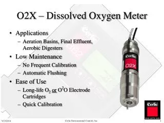
Market Research • Existing solutions: > $1000 • HACH LDO Process Dissolved Oxygen Probe $1565 • No remote capabilities • Market: over 100 M
Project Objective • Existing monitors and network • Account for temperature variation • Temperature sensor • DO level calculation modification • Ensure functioning mesh network • Test integrated units • Make necessary changes • Add new functionality
Functional Requirements • Required • The monitor units shall take readings of dissolved oxygen. • The monitor units shall wirelessly transmit their readings to the master controller. • The master controller shall request readings from each monitor unit. • The master controller should have a graphical user interface to display measurements. • The master controller user interface shall allow the user to poll a monitor unit for data. • The system shall query each monitor unit for data through the master controller. • The Windows service shall log all data processed through the unit in a SQL database. • The network nodes shall create a star-like topology • Optional • The network nodes shall create mesh network topology • The master controller shall send calibration data to each monitor unit.
Non-functional Requirements • The system shall have an optimal operating range of 1000 meters. • The microcontroller shall enter a sleep state between samples. • A temperature probe shall be attached to the existing sensor probe to increase calculated accuracy.
Constraints • Operating temperature: 0 to 50° Celsius. The temperature sensor must be accurate to ±1°C to satisfy this constraint. DO Monitor units need to be resistant to changes in temperature. • Operating environment: water resistant. The probe should be resistant to water damage. • Battery power is limited in sensor locations. The system needs to conserve as much power as possible when not measuring DO levels to ensure long battery life. • Existing implementation uses Zigbee. Zigbee modules cannot route while in sleep mode.
Risks • Circuit board redesign • Encountering circuit issues frequently • Existing design problems • Sleep prevents mesh network from functioning • Power is controlled by DO Monitor, not ZigBee node
Hardware Platforms • AtxMega128 • ZigBit Amp • Custom DO Sensor • Temperature Sensor: Temperature-to-Voltage • TC1047
Test Plan: DO Sensor • Temperature sensor • Verify voltage levels from temperature sensor. • Verify ADC conversion. • Verify temperature constraint extremes. • DO Sensor • Verify DO sensor readings at room temperature. • Verify DO sensor readings at various temperatures. • Verify device enters and exits sleep mode
Test Plan: ZigBee Node • Verify the ability of a ZigBee Node to receive a message. • Verify the ability of a ZigBee Node to transmit a message.
Test Plan: NW Coordinator; Master Controller • Network Coordinator • Verify the ability of a Network Coordinator to receive a message. • Verify the ability of a Network Coordinator to transmit a message. • Master Controller • Verify the ability of the Master Controller to send a command.
Test Plan: Integration Testing • Verify communication between the Master Controller (PC) and Network Coordinator. • Verify transmission of a command from the Network Coordinator to all ZigBee Nodes by verifying that the same command is read on all ZigBee Nodes. This is part of the star topology. • Verify transmission of data from any ZigBee Node to the Network Coordinator by verifying the same data was received by the Network Coordinator. This is also a part of the star topology. • [Optional] Verify a ZigBee Node is able to receive data from another ZigBee Node and able to pass it to the Network Coordinator. This makes a mesh network. • Repeat steps 1 - 4 with all command types.
Test Plan: System Testing • Verify power usage when in OFF state. • Verify the device enters sleep mode when not in use. • Confirm the user interaction of pressing the “Take Sample Now” button in GUI will result in new measurement data from all DO monitor units. • Confirm the user interaction ability to reconfigure coefficient calibrations on all DO monitor units.
Accomplishments Temperature sensor tested in hardware Hardware debugging Obtained necessary software stacks Some network testing Documentation clarified and expanded
Member Contributions David Hansen Extensive hardware critiquing and debugging Scott Mertz Hardware debugging Temperature sensor testing Betty Nguyen Network testing Setting up test framework Ashley Polkinghorn Network testing Setting up test framework
Next Semester… Building and testing two more boards Make Master Controller consistent with sleep mode design Possibly implement remote calibration Finish testing network components Finish implementing and testing temperature firmware Integration testing