Download
1 / 22
500 likes | 1.79k Views
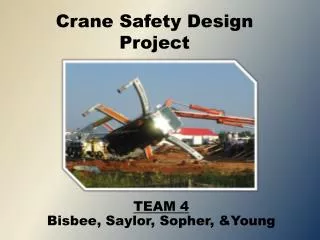
Design of Crane Runways According to CSA and CMAA. By: Victoria Lake. Outline. Introduction Types of Runways Typical Sections CSA Standards CMAA Standards Crane Classes Types of Loads Load Combinations Example Conclusion. Introduction.

E N D
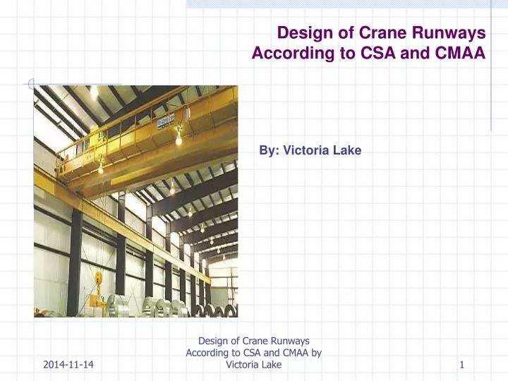
Design of Crane RunwaysAccording to CSA and CMAA By: Victoria Lake Design of Crane Runways According to CSA and CMAA by Victoria Lake
Outline • Introduction • Types of Runways • Typical Sections • CSA Standards • CMAA Standards • Crane Classes • Types of Loads • Load Combinations • Example • Conclusion Design of Crane Runways According to CSA and CMAA by Victoria Lake
Introduction • Runway is beam that supports crane bridge and trolley • Should be stiff to limit deflections • Special Considerations • Laterally unsupported, except at the columns • Subject to impact • Unsymmetrical bending due to lateral thrust from starting/stopping of crane trolley • Longitudinal loads due to starting/stopping of crane bridge • Greater Risk of Fatigue due to repeated loadings RUNWAY BEAMS Design of Crane Runways According to CSA and CMAA by Victoria Lake
Types of Cranes • Top Running • Under Running Design of Crane Runways According to CSA and CMAA by Victoria Lake
Common Runway Beam Sections • (a) wide flange rolled section • (b) wide flange with added plate to top flange • (c) wide flange with added channel to top flange • (d-h) other variations • (i) horizontal truss Design of Crane Runways According to CSA and CMAA by Victoria Lake
Manufacturer and Client Data • Manufacturer to provide: • Maximum wheel loads • Wheel spacing • Trolley weight • Clearances required • Client to provide: • Span • Capacity needed • Type of crane preferred • Length of runway Design of Crane Runways According to CSA and CMAA by Victoria Lake
CSA Standards • Limit States Design per CSA S16-01 • Appendix C: Crane Supporting Structures • Deflection • Vertical, capacity > 225kN, L/800 • Vertical, capacity < 225kN, L/600 • Lateral, L/600 • New Publication • CISC: Crane Supporting Steel Structures (2005) • Provides more detailed procedures and requirements Design of Crane Runways According to CSA and CMAA by Victoria Lake
CMAA Standards • Based on Allowable Stress Design • Procedure checks • Allowable stresses • Combined stresses • Buckling, local and lateral torsional • Longitudinal, vertical and diaphragm stiffeners • Deflection is limited to 1/600 length of the span • Camber not to exceed 1/888 length of the span Design of Crane Runways According to CSA and CMAA by Victoria Lake
Crane Classes (from CMAA and CSA) Design of Crane Runways According to CSA and CMAA by Victoria Lake
Principal Loads • Vertical Inertia Forces • Forces due to the motion of the crane or crane components • Forces due to lifting of the hoist load • Dead Load Factor (DLF) • applied the dead loads of the crane, trolley, and its associated equipment • Related to travel speed • Hoist Load Factor (HLF) • applied to the motion of the rated load in the vertical direction • Also inertia forces and the mass forces due to sudden lifting of the hoist load • Dead Load (DL) • weight of all elements of the bridge structure, the machinery parts and the fixed equipment supported by the structure • Trolley Load (TL) • Weight of trolley and any equipment attached to it • Lifted Load (LL) • The lifted load is the sum of the working load and the lifting devices used for handling and holding the load, for example the load block, lifting beam, bucket, magnet, and grab Design of Crane Runways According to CSA and CMAA by Victoria Lake
Principal Loads, cont… • Inertia Forces From Drives (IFD), also referred to as Side Thrust • Forces from acceleration, deceleration, trolley impact with end stop • Applied to both live and dead loads • CMAA: Lateral load is calculated as a percentage of the vertical load, 7.8 times the lateral acceleration or deceleration rate ( > 2.5% of the vertical load) • CISC: 20% of combined weight of lifted load and trolley (for cab-operated cranes) Design of Crane Runways According to CSA and CMAA by Victoria Lake
Additional Loads • Operating Wind Load (WLO) • outdoor crane is 5 lbs/ft2 of the projected area of the crane with is exposed to wind • should be divided equally between the 2 girders • Forces due to Skewing (SK) • horizontal forces normal to the rail from wheels • obtained multiplying the vertical load exerted on each wheel by coefficient Ssk which depends upon the ratio of the span to the wheel base Design of Crane Runways According to CSA and CMAA by Victoria Lake
Extraordinary Loads • Stored Wind Load (WLS) • maximum wind load that the crane can withstand when it is not in service • depends on the height of the crane above the ground, its geographical location, and its degree of exposure to prevailing winds • Collision Forces (CF) • Resulting from crane hitting bumper stops • Torsional Forces and Moments • Starting/stopping of bridge motors • Due to vertical loads • Due to lateral loads Design of Crane Runways According to CSA and CMAA by Victoria Lake
CMAA Load Combinations • Case 1 • regular use under principal loading (stress level 1) • Case 2 • regular use under principal and additional loading (stress level 2) • Case 3 • Subject to extraordinary loads (stress level 3) • applies mostly to outdoor cranes • Out of Service Wind • In collision • Test Loads Not more than 125% rated load Design of Crane Runways According to CSA and CMAA by Victoria Lake
CISC Load Combinations (vertical + side thrust) (C1 + impact + longitudinal) (vertical for multiple cranes + side thrust + long.) (vertical + side thrust + long., all multiple cranes) (vertical + side thrust + impact + long., all multiple) (vertical + side thrust, all multiple) (vertical + side thrust + bumper impact Design of Crane Runways According to CSA and CMAA by Victoria Lake
Example: Design Mono-symmetric Runway Beam Design of Crane Runways According to CSA and CMAA by Victoria Lake
Example: Load Diagram Design of Crane Runways According to CSA and CMAA by Victoria Lake
Example: Determine Moments and Side Thrust Design of Crane Runways According to CSA and CMAA by Victoria Lake
Example: Select trial section • In this case, W610x217 with a 381x12.7 cover plate is chosen Design of Crane Runways According to CSA and CMAA by Victoria Lake
Example: Subsequent Procedure • Calculate limiting unbraced length for plastic bending capacity and inelastic buckling • Calculate factored resistance • Calculate distribution of side thrust • Check overall member strength • Check stability (lateral torsional buckling) • Completes check for bending • Next: • Design stiffeners • Design bearings and lateral restraints • Design connections (welds and bolts) • Check fatigue resistance • After selection of trial section, the procedure is as follows: • Check class of section (S16-01, Clause 11.2) • Calculate plastic moment, Mp, and plastic section modulus, Z • Calculate elastic section properties (built-up) • Calculate section properties for mono-symmetric analysis (not covered in CSA, use CISC Section 5.9) • Check strength of section in bending Design of Crane Runways According to CSA and CMAA by Victoria Lake
Conclusion • Complicated procedure • Must design a stiff runway to prevent deflections • Also consider potential for fatigue due to repeated loading • Which standards to follow: CSA or CMAA? • CISC’s new “Guide to Crane Supporting Structures” provides good examples and information Design of Crane Runways According to CSA and CMAA by Victoria Lake
The end. Design of Crane Runways According to CSA and CMAA by Victoria Lake