Download
1 / 10
100 likes | 105 Views
This guide provides the necessary valve configurations and line setups for receiving and loading products at the terminal, including utilizing the Barge Suction Manifold and Tank Alignments.

E N D
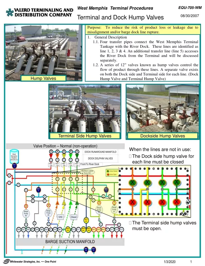
When the lines are not in use: • The Dock side hump valve for each line must be closed • The Terminal side hump valves must be open. Hump Valves Terminal Side Hump Valves Dockside Hump Valves
It may be necessary to receive product via the West Memphis Pipeline using the Barge Suction Manifold due to other product movements at the terminal occupying the receipt manifold. Example: receiving product from Teppco Pipeline. • Note: It is essential that both Hump Valves on line 3 are closed for this line-up. • The following valves must be open: • MOV 002 Main Line Block Valve • Pipeline Horizontal Gate Valve to Barge Suction Receipt Lineup • MOV 6 – Gasoline Lineup • Pump 3 Cross-over Gate Valve • Pump 3 Cross-over Bypass Valve • Main Gate Bypass Valve to Suction Manifold • Suction Manifold Splitter Valve (this example) • Appropriate Tank Valve on Suction Manifold (example 806) • The following valves must be closed: • Both Hump Valves on Line 3 (this example) • Pump 4 Cross-over Gate Valve • Pump 4 Cross-over Bypass Valve • Pump 4 Discharge MOV Valve • Pump 3 Discharge MOV Valve • Pump 4 Suction Gate Valve • Pump 3 Suction Gate Valve • Non Applicable Tank Valves on Suction Manifold • Pipeline MOV Valves 9, 10 & 11 Barge Product may be received utilizing the Suction Manifold. The diagram shows an example of receiving product from line 4, through the Suction Manifold and filling Tank 807. • The following valves must be open: • Dock Dolphin Valve on Line 4 • Dock Side Hump Valve on Line 4 • Line 4 Outboard Isolation Valve • Pump 4 Crossover Bypass Valve • Main Gate Bypass Valve to Barge Suction Manifold • Suction Manifold Splitter Valve • Manifold Valve to Tank 807 • The following valves must be closed: • Terminal Side Hump Valve on Line 4 • All non-applicable Dock Side Hump Valves (lines 3-2-1) • Pump 4 Crossover Pipeline Gate Valve • Pump 3 Crossover Bypass Valve • Pump 4 Discharge MOV Valve • All non-applicable Manifold Tank Valves
Barge Product is normally received with the following Valve and Tank Alignment. This example shows product being unloaded through line 4 to Tank 807. (An alternate (light purple line) tank 806 path is also shown) • The following valves must be open: • Dock Dolphin Valve on Line 4 • Dock Side Hump Valve on Line 4 • Terminal Side Hump Valve on Line 4 • 807 Tank Gate Valve • The following valves must be closed: • Dock Side Hump Valves to Lines 3-2&1 • Crossover Gate Valve from Pump 3 • Crossover Gate Valve from Pump 4 • Crossover Bypass Valve from Pump 3 • Crossover Bypass Valve from Pump 4 • Pump 3 Discharge MOV Valve • Pump 4 Discharge MOV Valve • All Valves on Barge Suction Manifold relating to gasoline receipts. • ALTERNATE to 806 (Open 902 valve on line 4 and 902 valve on line 3 – then 806 Tank Gate Valve. Tank 807 Valve must remain Closed.
Barge Loading – Standard Setup up on Line 4 • Detail • The following valves must be open: • Tank 807 Valve on Manifold • Pump 4 Suction Valve • Pump 4 Discharge MOV Valve • Line 4 Outboard Isolation Valve • Dock Side Hump Valve on Line 4 • Dock Dolphin Valve on Line 4 • The following valves must be closed: • Pump 4 Crossover Bypass Valve • Pump 4 Crossover Gate Valve • Terminal Side Hump Valve on Line 4 • All non-applicable Dock Side Hump Valves Barge Loading when Loading with a specific line Pump to a different Line. • Detail • The following valves must be open: • Tank 807 Valve on Manifold • Pump 4 Suction Valve • Pump 4 Discharge MOV Valve • Pump 4 Crossover Bypass Valve • Pump 3 Crossover Bypass Valve • Terminal Side Hump Valve on Line 4 • Dock Side Hump Valve on Line 3 • The following valves must be closed: • All non-applicable tank valves on manifold • Line 4 Outboard Isolation Valve • Pump 4 Crossover Gate Valve • Pump 3 Crossover Gate Valve • Dock Side Hump Valve on Line 4 • Terminal Side Hump Valve on Line 4
Receiving WM Pipeline at the Barge Suction Manifold • The following valves must be open: • MOV 2 on West Memphis Pipeline • MOV 11 • Tank 810 Valve • The following valves must be closed: • MOV 6 – Gasoline Lineup • MOV 7 – Fuel Lineup • MOV 9 • MOV 10 • All Non Applicable Valves on Pipeline Gasoline Receipt Header • Tank Valve 810 on Line 3
In-House Line Wash Runaround • Detail • The following valves must be open: • Tank 808 Valve on Manifold • Pump 3 Suction Valve • Pump 3 Discharge Valve • Dockside Hump Valve on Line 3 • Dock Dolphin Valve on Line 3 • Dock Runaround Manifold Valve on Line 3 • Dock Runaround Manifold Valve on Line 4 • Dock Dolphin Valve on Line 4 • Dockside Hump Valve on Line 4 • Terminal Side Hump Valve on Line 4 • Tank 807 Valve • The following valves must be closed: • All non applicable Tank Valves on manifold • Pump 4 Discharge Valve • Pump 4 Crossover Bypass Valve • Pump 4 Crossover Gate Valve • Line 4 Outboard Isolation Valve • Pump 3 Crossover Gate Valve • Pump 3 Crossover Bypass Valve • Terminal Side Hump Valve on Line 3 • All non-applicable Dockside Hump Valves • All non-applicable Dock Dolphin Valves • All non-applicable Dock Runaround Manifold valves • All Line 3 Tank Valves • All non-applicable line 4 Tank Valves • All non-applicable tank valves on Tank 902 line • Gate Valve end of Line 4 • Gate Valve end of Line 3
Tank to Tank Transfer (example from 807 to 806) • The following valves must be open: • Tank 807 Valve on Manifold • Pump 4 Suction Valve • Pump 4 Discharge Valve • Line 4 Outboard Isolation Valve • Terminal Side Hump Valve on Line 4 • Tank 902 valve on line 4 • Tank 902 Valve on line 3 • Tank 806 Valve • The following valves must be closed:\ • All non-applicable Tank Valves on Manifold • Pump 4 Crossover Bypass Valve • Pump 4 Crossover Gate Valve • Pump 3 Crossover Bypass Valve • Pump 3 Crossover Gate Valve • Pump 3 Discharge Valve • Dock Side Hump Valve on Line 3 • Dock Dolphin Valve on Line 3 • All non-applicable tank valves on line 4 • All non-applicable Tank 902 valves on 902 line • All non-applicable Tank Valves on line 3 • Gate Valve end of Line 4 • Gate Valve end of Line 3
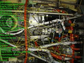
MOV 002 on West Memphis Pipeline Pipeline Horizontal Gate Valve to Barge Suction Receipt Lineup Dock Side Hump Valve on Line 4 Dock Side Hump Valves MOV 2 Terminal Side Hump Valves MOV 7 – Fuel Lineup MOV 6 – Gasoline Lineup Line 4 Outboard Isolation Valve Line 3 Crossover Gate Valve Pump 4 Crossover Gate Valve Pump 3 Crossover Bypass Valve Pump 4 Crossover Bypass Valve Pump 3 MOV Discharge Valve Shorthorn Lateral MOV Valves Pump 4 MOV Discharge Valve Main Gate Bypass Valve to Barge Suction Manifold Suction Manifold Splitter Valve Pump 4 Suction Valve Tank Valves on Barge Suction Manifold MOV 9 Tank Valves 902 Gate Valves