Download
1 / 44
480 likes | 652 Views
Introduction to drainage theory and practice. Introduction Problem is mainly the reduction in the respiration rate caused by reduced oxygen supply. Groundwater drainage refers to the artificial removal of water by lowering the water table. References.

E N D
Introduction Problem is mainly the reduction in the respiration rate caused by reduced oxygen supply. Groundwater drainage refers to the artificial removal of water by lowering the water table.
References Hillel, D. 1998. Environmental soil physics. Academic Luthin, J.N. 1957. Drainage of agricultural lands. Amer. Soc. Agron. Marshall, T.J.; Holmes, J.W. 1979.Soil physics. CUP Ochs, W.J.; Bishay, G.B. 1992. Drainage guidelines. World Bank Technical Paper no. 195 Rycroft, D.; Amer, M.H. 1995. Prospects for drainage of clay soils. FAO Irrigation & Drainage Paper 51 US Dept. of Interior, Bureau of Reclamation. 1978. Drainage manual. USDI
Web site containing list of computer models for drainage, irrigation, hydrology http://www.wiz.uni-kassel.de/kww/irrisoft/all/all_i.html
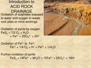
Water-logged soils • gas exchange only near the surface. • within the profile, O2 may be absent & CO2 may accumulate • reduction toxic concentrations of ferrous, sulphide, and manganous ions • OM methane • nitrification prevented • plant, especially fungal/root diseases are more prevalent • plants may suffer from moisture stress if grown in waterlogged soils and water table drops • soils more susceptible to compaction by animals & traffic
clogging of machinery • greater heat capacity so more difficult to warm up in spring • heat loss by evaporation greater • germination and early growth retarded • plant sensitivity to restricted drainage affected by temperature since rise in temperature is accompanied by decline in O2 solubility • high evaporation in a warm climate from • waterlogged soils leads to concentration of salts • at the surface - can only be removed by lowering • the water table through drainage (or growing salt • tolerant crops - only a temporary solution);
Causes of waterlogging • shallow ground water - e.g. riparian zones • “perched” water table - clay parent material or impervious rock • hydraulic properties of the soil • over-irrigation
Clay soils • vertisols - shrinking and swelling • infiltration and structure - bypass flow through shrinkage cracks, root channels, worm holes and horizontally along ped faces; • infiltration approximately linear : • Vi = Vc + Ist • Vc is the crack volume (m3/m2) • Vi is infiltrated volume • hydraulic conductivity typically 0.1 to 1 mm hr-1
non-Darcy flow • if K sat were used without modifications in usual drainage equations, spacings would be too close and so uneconomic - influence of sub-soiling • drainage changes the actual values K (because of structural changes): • Changes in K follow the sequence: • K(tiles + surface) • > K(tiles) • > K(surface drains) • > undrained
various models exist which relate clay content, crack dimensions and bypass flow to conductivity (e.g. LEACHW (Wangenet & Hutson, 1989; Booltink, 1993))- Booltink modified model to calculate bypass flow based on physical and morphological factors
Surface • beds /furrows • ditches
open drains - interfere with operations, weeds, pests, but easy to monitor
Subsurface involving modification to structure • Mole drainage • Gravel tunnel • Subsoiling • These methods are suitable only for soils with high clay content – if clay content is too low, the unlined drainage lines would collapse. • Design is very much done by rule of thumb and • local experience. • Little in the way of determinative design.
Drainage by means of ditches or underground pipes to control the height of the water table Introduction • examples of the application of Darcy’s law to the development of models for drainage • ditches • underground pipes • control height of water table or remove excess water from soil with low hydraulic conductivities. • drainage improves hydraulic conductivity and vice versa.
Flow rate to drains depends on: • hydraulic conductivity of the soil: • anisotropy; • texture; • soil profile • configuration of water table :- • localised (alluvial), • regional, • perched, • artesian or sub-artesian • depth of drain; • outlet condition - no flow if submerged
slope and diameter of subsurface drains (or cross-sectional area of ditches) must be sufficient to lead water away; • ochre deposits due to reduced iron and manganese or salt deposits such as gypsum reduce the diameter - need oversizing as well as flushing out; • spacing
type of drains - clay tiles or slotted plastic • use of envelope - gravel reduces clogging and increases seepage surface; • rate at which excess water reaches groundwater - often taken as difference between rainfall and evapotranspiration but there will also be a natural drainage rate which occurs without artificial drainage
Steady flow v. transient flow solutions • steady flow solutions assume constant infiltration rate (even when it is not raining!) • transient flow solutions try to allow for the fluctuation in the water table due to intermittent rainfall or irrigation - much more difficult to solve mathematically
Adjustment of K, x and y values to allow for anisotropy Conductivity,. especially in clay soils, will usually be different in the vertical & horizontal directions - the conductivity in this case is said to be isotropic. A simple method is used to derive a single value for use in drainage calculations:
As well as using this composite value for K, modified values for depth (y) are used: x/ = x (i.e. x is unchanged) y/ = yA in which A is the anisotropic ratio, Kx/Ky
Depuit-Forcheimer (DF) soils A DF soil assumes: (a) for small inclinations of a water table in a gravity flow system, the streamlines can be taken as horizontal, i.e. the water has no vertical component of flow (b) the velocities along the streamlines are proportional to the slope of the water table The assumption is widely used and often produces solutions which are comparable to more rigorous treatments
In effect, the DF solution imagines the soil to be divided into a lot of narrow vertical slabs ---
Hooghoudt method for ditch drainage • Like many others, Hooghoudt’s method over- • simplifies the field situation but even so gives useful solutions. • The method assumes: • isotropic and constant K • parallel and equally spaced drains • hydraulic gradient is equal to the slope of the water table • Darcy’s law applies • impervious layer exists • constant flux • the soil is a Depuit-Forcheimer (DF) soil
q x
DF solution assumes that there are no streamlines below the bottom of the impermeable layer. • solution seems to be a good enough approximation for water table surface (though not for the route the water takes to the drain) Consider length of drain (i.e. into the paper) of 1 metre. Assume water passing horizontally through an arbitrary plane is product of downward flux, q (normally mm/day but here we use metres/sec so that units are consistent) and the distance between the plane and the mid-point between the drains Q = -q (S/2 - x) x 1 metre
From Darcy’s Law, horizontal flux at plane is: Total flux through the section: The hydraulic potential is taken as the height of water table above the impervious layer, i.e. a DF soil. Equating the two expressions for Q:
So: The water table varies from D to (H + D) above the impermeable layer, so integrating:
Referring to the diagram, since b = H-D, this can be rewritten as which is the equation of an ellipse. The above equation can also be written as Since b-D = H and (b+D)/2 is the average depth that the water can flow through, this can in turn be written as :-
is the average depth that the water where flows through This idea has been extended to the situation where the bottom of the ditch does not rest on an impermeable layer though it pushes the theory even further beyond its proper limits - but still seems to work Note in practice an impermeable layer is one that has a K of say less than <10% of the overlying soil
Web sites for Hooghoudt’s solution and a calculator for drain spacing :- http://www.geocities.com/CapeCanaveral/Hall/5606/calculat/ground1.htm http://www.sedlab.olemiss.edu/java/Hooghoudt_java.html
Hooghoudt envisaged a “virtual” drain and modified the ditch equation to : where