Download
1 / 19
680 likes | 1.51k Views
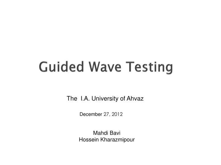
Guided Wave Testing. The I.A. University of Ahvaz. December 27, 2012. Mahdi Bavi Hossein Kharazmipour. DEFINITION. Guided waves are ultrasonic waves that propagate along the length of a structure, guided by and confined in the geometric boundaries of the structure. Flange.

E N D
Guided Wave Testing The I.A. University of Ahvaz December 27, 2012 MahdiBavi HosseinKharazmipour
DEFINITION Guided waves are ultrasonic waves that propagate along the length of a structure, guided by and confined in the geometric boundaries of the structure
Flange Conventional Ultrasonic Test Localized Inspection Weld Metal loss Metal loss Guided Wave 100% Inspection Metal loss Weld Metal loss • The difference in concept between UT and GWT Conventional UT measures the wall thickness at a spot , while GWT can identify locations of metal loss along a length of the pipe Conventional ultrasonic inspection provides a local thickness measurement GWUT Inspection provides detection of both internal and external corrosion
The differences between conventional UT waves and guided waves • Guided waves are bulk waves; therefore the entire volume of the pipe is inspected • Frequencies used in guided wave inspection are much lower than conventional ultrasonic testing; therefore the wave lengths are much longer and are scattered instead of reflected from changes in the dimension of the wave guide • The pipe acts as a wave guide, permitting the waves to travel long distances • The waves can be introduced at a single location: • When introduced with piezoelectric crystals an array of transducers are used. • Coils of wire are used to create vibrations in the pipe via the magnetostrictiveeffect
Longitudinal Torsional Flexural The waves used in the GWT
Guided waves are introduced into the pipe by one of two systems: • An array of piezoelectric crystals are positioned in modules that typically hold two transducers each. The modules are spaced around the pipe under an air bladder which when pressurized forces the units against the surface. The individual crystals oscillate at the frequency at which they are excited and transmit the wave into the pipe.
Coils of insulated wire are wrapped around the pipe. An alternating current is passed through the coils, and an oscillating magnetic field is produced. Due to the magnetostrictive effect ,this produces a wave in the pipe which can be amplified by using a nickel or cobalt strip bonded to the pipe under the coil.
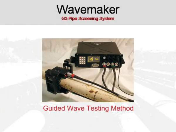
The power and durability of today’s electronics has made it possible to field the GWUT system in a compact package Monitor Umbilical cable connecting electronics to transducers Pressurized bladder containing the array of piezoelectric crystals Field electronics
Example of graphical data display Weld Area of corrosion Weld
Example of graphical data display DistanceAmplitude Correction (DAC) Curves Weld Welds at two elbows • Minor Anomaly
Some Advantages of Guided Wave Ultrasonic Testing • Can test long distances of pipe from a single access point • Has developed into an effective screening tool useful in locating and ranking areas of corrosion; thereby minimizing the amount of follow-up inspection needed to determine the integrity of piping. • Can be used on in-service pipelines • Both internal and external corrosion can be identified • Current commercial systems are packaged in a small number of durable components. The systems are easily transported and quickly setup in the field with preliminary results available at the time of the test
Some Limitations of Guided Wave Ultrasonic Testing • Complicated evaluation of data by highly trained operators is required because of the complex signals involved • Dimensions of corrosion cannot be directly determined • Significant corrosion can be missed, especially localized damage • The scattered signal cannot be directly equated to a specific area or volume of loss due to a lack of an absolute calibration standard • Many field conditions exist that limit the distances that can be effectively inspected and that cause artifacts which can complicate analysis. • The tests identify change in cross-sectional area, and can miss corrosion that is general in nature, is in the configuration of grooves that pass under the array, or are too small to detect
The conditions that can limit the distance of a piping segment that can be reliably inspected • various coating such as coal tar epoxies, asphalt-tar wraps, concrete, etc, • plastic sleeves, particularly those with internal mastics • wet insulation, particularly if ice is present • rough internal or external surfaces • direct buried pipe, particularly in situations where heavy or wet soil is encountered • dense product, internal build up of solids, and situations with variable product flow • system noise created by factors such as turbulent product flow or pumps • temperature variations and gradients that can lead to changes in the wave velocity
Pit located on 10” Schedule 80 pipe (0.15 in deep x 4.5 in x 3 in)
Example of corrosion that would not have been noted with Guided Wave on a buried piping segment • This is a photograph of the corroded area which caused the leak in a buried 6” line. • Along the line drawn, the cross-sectional area of the ½” walled pipe is approximately 9.62 square inches, while the area lost to corrosion through the hole is 0.5 square inches. • this is a loss of approximately 5.2% of the cross-section. It would not been seen in a scan since the section was buried. However, if this line was above-ground and exposed the corrosion probably would have been noted as a minor anomaly
Weld profiles are assumed to be uniform along the length of the tested segment, and represent some arbitrary percent change in cross-sectional area, typically 25% CSC. There is no absolute calibration standard.This can compromise the accuracy of the results and can even lead to miss-calls, as in the case below. The high-low condition extended around approximately one-forth of the circumference, created an asymmetrical response, and was therefore ranked as a moderate anomaly.
Conclusions • Guided wave offers valuable new inspection technology if it’s capabilities and limitations are kept in mind. • It is a SCREENING tool. Need to follow up with other NDT techniques to quantify / evaluate possible defects. • If used without other verification, GWT cannot provide the level of detail needed to ascertain the integrity of piping. • Main advantage is the ability to screen long sections of pipe to determine overall, general condition and locate areas that require more detailed examination.