Download
1 / 97
3.48k likes | 6.34k Views
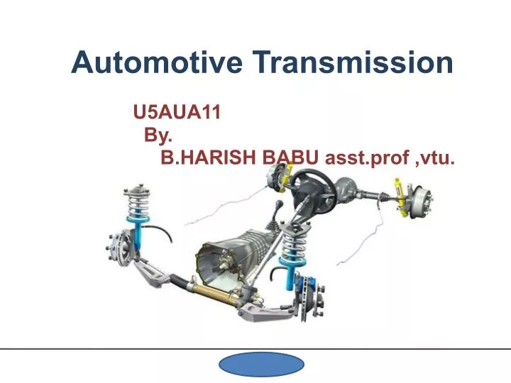
Automotive Transmission. U5AUA11 By. B.HARISH BABU asst.prof , vtu. UNIT I. Contents. Introduction. Transmission Systems. Manual. Automated Manual Automatic. Continuously variable Dual Clutch. Propeller Shaft. 2. Contents.

E N D
Automotive Transmission U5AUA11 By. B.HARISH BABU asst.prof ,vtu.
Contents Introduction Transmission Systems Manual Automated Manual Automatic Continuously variable Dual Clutch Propeller Shaft 2
Contents Universal joints Differential Requirements of the Transmission Design Process Product Life Cycle Stages in the Design Process • Project Set Up • Concept Design • Detailed Design • Engineering Drawings and Tolerancing 3
Transmission System • Function of transmission: - It is used to transmit engine torque to the drivingwheels to drive the vehicle on the road. 4
Requirement of Transmission System • To provide for disconnecting the engine from thedriving wheels • When engine is running , connect the drivingwheels to engine smoothly without shock • Leverage between engine and driving wheels tobe varied • Enable the driving wheels to rotate at differentspeeds. • Provide relative movement between engine anddriving wheels 5
Clutch Function of clutch • Clutch is used to disengage and engage theengine with rest of the transmission systems. • To disengage while starting the engine andwhile changing gear ratio. • To engage after starting of the engine and gearshift operation. 8
Clutch Requirement of Clutch • Transmit maximum torque of the engine. • Engage gradually to avoid sudden jerks. • Dissipate maximum amount of heat. • Damp the vibrations and noise. • Dynamically balanced. • As small as possible. • Easy to operate. 9
Clutch Unit • Flywheel also acts as a driving member • Pressure plate is connected to clutch cover assembly. • Clutch Cover assembly is bolted to the flywheel. • Clutch springs placed between Pressure plate & Cover plate, press the Pressure plate against the clutch plate. • Thus Clutch plate is squeezed between Flywheel & Pressure plate.
Classification of Clutch • Cone clutch • Flat Plate clutch - Dry or Wet type clutch - No. of friction plates(Single or Multiple) - Actuation mode (Cable orHydraulic) - Actuation spring (Helical or Diaphragm) • Centrifugal clutch 11
Clutch Engaged & Disengaged • Clutch is always is in engaged state. • It can be disengaged by pressing of Clutch pedal. Disengagement is effected by non - contact of Clutch plate both with Flywheelface & Pressure plate face. • Frictional heat is dissipated by openings present in Clutch housing& Cover 12
Gear Box • Gear box varies the leverage (speed ratio & hence torque ratio) between the engine & driving wheels. • It is located between Clutch & Propeller shaft. • It is provided with either 4 speed or 5 speed ratios or more depending on design. • Gear ratio is varied by Gear shift lever. 15
Synchronizers • A device used to bring two adjacent members to the same speed before allowing the sleeve to engage them. • The two elements are friction clutch and toothed clutch. • Lock the positive engagement until speeds are synchronized . • Establish the positive engagement and power flow. • Synchronizer is splined on the shaft Cone on the gear (blue) fits into cone-shaped area in the collar. • Friction between the cone and collar synchronize the collar & gear. • The outer portion of the collar (sleeve) then slides so that the dogteeth engage the gear. 17
Synchromesh Gearbox 1.I speed gear 2.II speed gear 3.main shaft 4.outer engaging unit 5.inner engaging unit 6.top gear engaging teeth 7.main drive gear 8.top gear synchronizing cones 9.counter shaft 18
How Manual Transmission Work? • When a driver wants to change from one gear to another in a standard stick-shift car, he first presses down the clutch pedal • This operates a single clutch, which disconnects the engine from the gearbox and interrupts power flow to the transmission • Then the driver uses the stick shift to select a new gear, a process that involves moving a toothed collar from one gear wheel to another gear wheel of a different size • Devices called synchronizers match the gears before they are engaged to prevent grinding • Once the new gear is engaged, the driver releases the clutch pedal, which re-connects the engine to the gearbox and transmits power to the wheels. 19
Manual Transmission • Cheap to make • Durable, efficient • Easy to install • Established in marketplace and withmanufacturing infrastructure • Gives control to the driver • But driver comfort an issue with increasing trafficdensity Hence automation must be considered 20
Automated Manual Transmission (AMT) • Automation of Clutch and Gear shifting operations • Elimination of ClutchPedal • Modification of GearShifting lever • Minimum modifications in manual transmission 21
AMT Features • Automation of Clutch operation and Gearshifting. • Clutch slip control during starting • Hill start aid system which will assist the driver inhold and move the vehicle in hill slope • Necessary fail safe systems such as suddenshifting from higher gear to lowest gear and vice versa 22
Clutch Actuation Control • Engine Start - Starter should be operated only when the gear isin neutral position - When engine is not running and in power on, ECUwill disengage clutch - When engine speed exceeds a specified rpm, ECUengages clutch gradually • Vehicle Start - On pressing the accelerator pedal, ECU controlsthe clutch - actuator travel and clutch engagement 24
Clutch Actuation Control • Gear Change - While engaging the clutch after gearshift, the ECU determines clutch actuator travel based on shifted gear position andaccelerator pedal stroke • Clutch disengagement - While gear shifting and when acceleratorpedal is released, - if the vehicle speed is lower than a setspeed for select gear position, the ECU disengages clutch 25
Advantages of AMT • Reduced driver effort • Improved Clutch life • Utilization of existing manufacturing facilitiesfor manual transmission • Lower production cost than automatictransmissions • Higher efficiency than automatictransmissions 26
Automatic Transmission (AT) Conventional Definition • Moving away from rest - Torque converter • Achieving ratio change - Planetary gear sets • No power interruption • Mechanism for ratio change - Wet plate clutches and brakes • Control of ratio change - Normally automatic timing and actuation 27
Fluid Coupling • Converts or transmits rotating mechanical energy or power. • Basic components. - outer shell or housing, - impeller or pump and turbine or runner • Both of these units are contained within the housing via oil-tight seals. • The input turbine is connected to the power supply, typically an electric or ICE. • The output turbine is connected to the drive train of the vehicle or the drive system of a machine. • Mineral oil is used 28
Fluid Coupling: Working • Standstill - The entire operating fluid in the coupling is at rest • Idling - In sufficient centrifugal force for the oil to turn the turbine • Low to medium speed: - Centrifugal force pushes oil into turbine and some turning effort is transmitted. Large degree of slip in the unit. O/p shaft is rotating slowly than input shaft. • Medium to High Speed - Oil force is sufficient to transmit full power. O/p shaft rotating at about 98% of speed of I/p shaft (2% slip). 29
Torque Convertor • Serves as automatic clutch which transmits engine torque to the transmission input shaft • Multiplies torque generated by the engine • Absorbs torsional vibration of engine • Acts as a flywheel and smoothes out engine rotation • Drives oil pump • A torque converter consists of - Impeller - Turbine - Stator - and transmission fluid 30
Impeller 32
Turbine 33
Stator 34
Working of Torque Convertor Vehicle accelerates 35
Planetary Gear System: Construction • Input shaft is connected to Ring gear(Blue) • Output shaft is connected to Plane carrier(Green) which is also connected to Multi-disk clutch • Sun gear is connected to a Drum(Yellow), which can be locked by brake band (Red). It is also connected to the other half of Clutch 37
Planetary Gear System: Operation • In Neutral Both band and clutch sets are released • • Planets assembled to carrier with NRB • Ring gear only drive planet gear not the planet carrier (Output shaft) • The planet gears drive the sun gears to spin freely 38
Planetary Gear System: Operation • In Low Gear (forward reduction) • Band locks the sun gear by locking the drum • Planets walk around the sun gear • Planet carrier to spin in same direction as ring gear • Gear ratio= sun & ring teeth/no of teeth of ring gear 39
Planetary Gear System: Operation • In High Gear (Direct drive) • Band is released. • Lock any two members • Clutch is engaged so that the sun gear and planet carrier is locked to act as a rigid member • Planets has to walk around the ring gear, • Ring Gear (Input shaft) will spin at the same speed as the Planet Carrier (Output shaft) 40
Planetary Gear System: Operation • Reverse Gear • Planet carrier is locked • Ring gear (Input shaft) will cause the sun gear(Output Shaft) to turn in the opposite direction 41
Automatic Transmission (AT) Advantages The only option for comfortable automatic shiftingCost issue mitigated by high volume manufacturing Disadvantages Cost for development and manufacturingFuel economy due to torque converter Lack of control by the driver Modern improvements Better control algorithmsTorque converter lock up Most useable transmissions based on a couple of standard arrangements Ravigneaux Lepelletier 42
Continuously Variable Transmission (CVT) • CVT provides infinite number of gear ratios (between a minimum & amaximum). • Shifts automatically with an infinite number of ratios • Seamless power delivery, no torque interruption & power loss 43
CVT: Construction Uses a pair of axially adjustable sets of pulley halves (Variators) Both pulleys have one fixed and one adjustable pulley halve A “belt” is used to transfers the engine'spower from one shaft to another 44
CVT: Functioning • The transmission ratio is varied by adjusting the spacing between the pulleys in line with the circumference of the tapered pulley halves. • The variators are adjusted hydraulically. • When one pulley is varied, the other pulley must adapt itself inversely since the length of the belt is fixed.